MAS3559F 查看數據表(PDF) - Micronas
零件编号
产品描述 (功能)
生产厂家
MAS3559F Datasheet PDF : 92 Pages
| |||
MAS 35x9F
DATA SHEET
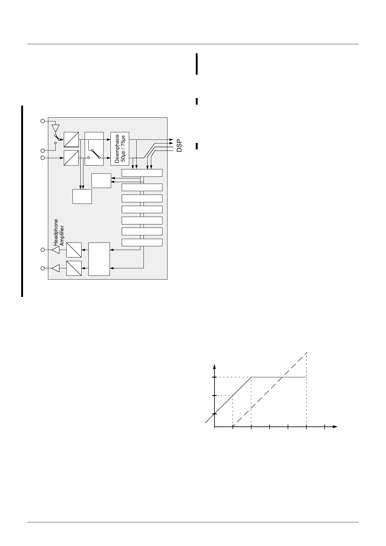
2.4. Audio Codec
A sophisticated set of audio converters and sound fea-
tures has been implemented to comply with various
kinds of operating environments that range up to high-
end equipment (see Fig. 2–4).
Mic-In
Line-In
Output
Mic-Amplifier incl. Bias
A
Mono
D
A
D
Q-peak
Q-peak
Audio
Codec
D
A
Volume
D Balance
A
Mixer
Mono/Stereo
AVC
Bass/Treble
Loudness
MB
Right invert
Fig. 2–4: Signal flow block diagram of Audio Codec
2.4.1. A/D Converter and Microphone Amplifier
A pair of A/D converters is provided for recording or
loop-through purposes. In addition, a microphone
amplifier including voltage supply function for an elec-
tret type microphone has been integrated.
2.4.2. Baseband Processing
The several baseband functions are applied to the dig-
ital audio signal immediately before D/A conversion.
2.4.2.1. Bass, Treble, and Loudness
Standard baseband functions such as bass, treble,
and loudness are provided (refer to Table 3–16 for
details).
2.4.2.2. Micronas Bass (MB)
The Micronas Bass system (MB) was developed to
extend the frequency range of loudspeakers or head-
phones below the cutoff frequency of the speakers.
Apart from dynamically amplifying the low-frequency
bass signals, the MB exploits the psycho-acoustic phe-
nomenon of the ‘missing fundamental’. Adding har-
monics of the frequency components below the cutoff
frequency gives the impression of actually hearing the
low frequency fundamental, while at the same time
retaining the loudness of the original signal. Due to the
parametric implementation of the MB, it can be cus-
tomized to create different bass effects and adapted to
various loudspeaker characteristics (see
Section 3.4.4. and Table 3–16).
2.4.2.3. Automatic Volume Control (AVC)
In a collection of tracks from different sources fairly
often the average volume level varies. Especially in a
noisy listening environment the user must adjust the
volume to comfortably enjoy listening. The Automatic
Volume Correction (AVC) solves this problem by
equalizing the volume level.
To prevent clipping, the AVC's gain decreases quickly
in dynamic boost conditions. To suppress oscillation
effects, the gain increases rather slowly for low level
inputs. The decay time is programmable by means of
the AVC register (see Table 3–16 on page 46).
For input levels of -18 dBr to 0 dBr, the AVC maintains
a fixed output level of -9 dBr. Fig. 2–5 shows the AVC
output level versus its input level. For volume and
baseband registers set to 0 dB, a level of 0 dBr corre-
sponds to full scale input/output.
output level
dBr
−9
AVCon
AVCoff
−15
−21
input level
dBr
−30 −24 −18 −12 −6
0 +6
Fig. 2–5: Simplified AVC characteristics
2.4.2.4. Balance and Volume
To minimize quantization noise, the main volume con-
trol is automatically split into a digital and an analog
part. The volume range is −114...+12 dB with an addi-
tional mute position. A balance function is provided.
10
June 30, 2004; 6251-505-1DS
Micronas
Share Link: 