MAX114 وں¥çœ‹و•¸و“ڑè،¨ï¼ˆPDF) - Maxim Integrated
零ن»¶ç¼–هڈ·
ن؛§ه“پوڈڈè؟° (هٹں能)
ç”ںن؛§هژ‚ه®¶
MAX114 Datasheet PDF : 12 Pages
| |||
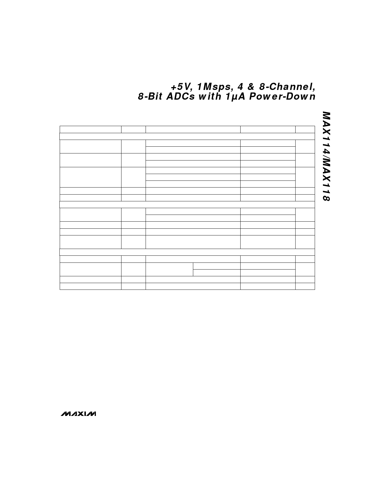
+5V, 1Msps, 4 & 8-Channel,
8-Bit ADCs with 1آµA Power-Down
ELECTRICAL CHARACTERISTICS (continued)
(VDD = +5V آ±5%, REF+ = 5V, REF- = GND, Read Mode (MODE = GND), TA = TMIN to TMAX, unless otherwise noted.)
PARAMETER
LOGIC INPUTS
Input High Voltage
Input Low Voltage
Input High Current
Input Low Current
Input Capacitance (Note 2)
LOGIC OUTPUTS
Output Low Voltage
Output High Voltage
Three-State Current
Three-State Capacitance
(Note 2)
POWER REQUIREMENTS
Supply Voltage
VDD Supply Current
Power-Down VDD Current
Power-Supply Rejection
SYMBOL
CONDITIONS
VINH
VINL
IINH
IINL
CIN
CS, WR, RD, PWRDN, A0, A1, A2
MODE
CS, WR, RD, PWRDN, A0, A1, A2
MODE
CS, RD, PWRDN, A0, A1, A2
WR
MODE
CS, WR, RD, PWRDN, MODE, A0, A1, A2
CS, WR, RD, PWRDN, MODE, A0, A1, A2
VOL
VOH
ILKG
COUT
ISINK = 1.6mA, INT, D0–D7
RDY, ISINK = 2.6mA
ISOURCE = 360آµA, INT, D0–D7
D0–D7, RDY, digital outputs = 0V to VDD
D0–D7, RDY
VDD
IDD
CS = RD = 0V,
PWRDN = VDD
MAX11_C
MAX11_E/M
CS = RD = VDD, PWRDN = 0V (Note 3)
PSR
VDD = 4.75V to 5.25V, VREF = 4.75V
MIN TYP MAX
2.4
3.5
0.8
1.5
آ±1
آ±3
50
200
آ±1
5
8
0.4
0.4
4
آ±3
5
8
4.75
5.25
8
15
8
20
1
10
آ±1/16 آ±1/4
Note 2: Guaranteed by design.
Note 3: Power-down current increases if logic inputs are not driven to GND or VDD.
UNITS
V
V
آµA
آµA
pF
V
V
آµA
pF
V
mA
آµA
LSB
_______________________________________________________________________________________ 3
Share Link: 