MAX17043 查看數據表(PDF) - Maxim Integrated
零件编号
产品描述 (功能)
生产厂家
MAX17043 Datasheet PDF : 14 Pages
| |||
MAX17043/MAX17044
1-Cell/2-Cell Fuel Gauge with
ModelGauge and Low-Battery Alert
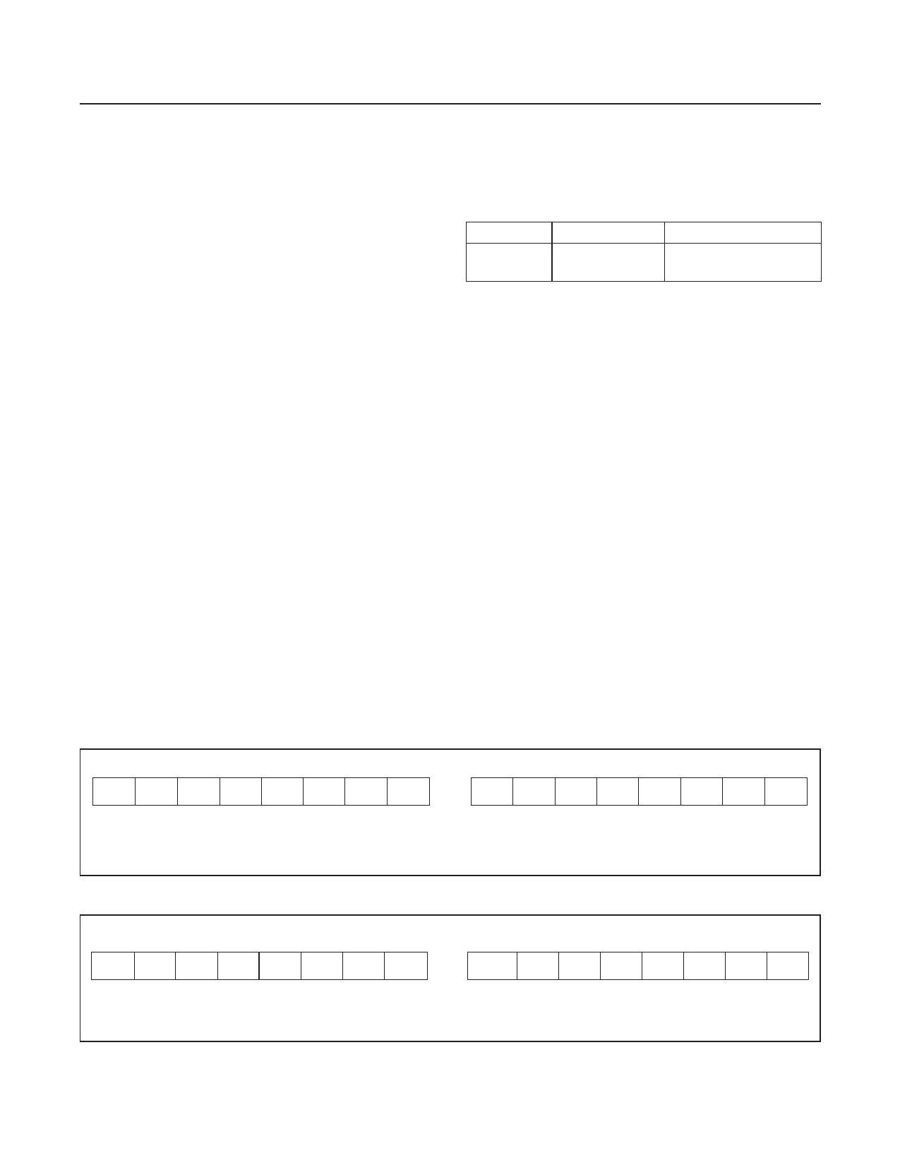
VCELL Register
Battery voltage is measured at the CELL pin input
with respect to GND over a 0 to 5.00V range for the
MAX17043 and 0 to 10.00V for the MAX17044 with
resolutions of 1.25mV and 2.50mV, respectively. The A/D
calculates the average cell voltage for a period of 125ms
after IC POR and then for a period of 500ms for every
cycle afterwards. The VCELL register requires 500ms to
update after exiting Sleep mode. The result is placed in
the VCELL register at the end of each conversion period.
Figure 3 shows the VCELL register format.
SOC Register
The SOC register is a read-only register that displays
the state of charge of the cell as calculated by the
ModelGauge algorithm. The result is displayed as a
percentage of the cell’s full capacity. This register auto-
matically adapts to variation in battery size since the
MAX17043/MAX17044 naturally recognize relative SOC.
Units of % can be directly determined by observing only
the high byte of the SOC register. The low byte provides
additional resolution in units 1/256%. The reported SOC
also includes residual capacity, which might not be avail-
able to the actual application because of early termination
voltage requirements. When SOC() = 0, typical applica-
tions have no remaining capacity.
The first update occurs within 250ms after POR of the IC.
Subsequent updates occur at variable intervals depending
on application conditions. ModelGauge calculations out-
side the register are clamped at minimum and maximum
register limits. Figure 4 shows the SOC register format.
Table 2. MODE Register Commands
VALUE
4000h
COMMAND
Quick-Start
DESCRIPTION
See the Quick-Start
description section.
MODE Register
The MODE register allows the host processor to send
special commands to the IC (Table 2). Valid MODE reg-
ister write values are listed as follows. All other MODE
register values are reserved.
VERSION Register
The VERSION register is a read-only register that con-
tains a value indicating the production version of the
MAX17043/MAX17044.
CONFIG Register
The CONFIG register compensates the ModelGauge
algorithm, controls the alert interrupt feature, and forces
the IC into Sleep mode through software. The format of
CONFIG is shown in Figure 5.
CONFIG
CONFIG is an 8-bit value that can be adjusted to optimize
IC performance for different lithium chemistries or differ-
ent operating temperatures. Contact Maxim for instruc-
tions for optimization. The power-up default value for
CONFIG is 97h.
MSB—ADDRESS 02h
211 210 29
28
27
26
25
24
MSB
LSB
0: BITS ALWAYS READ LOGIC 0
Figure 3. VCELL Register Format
LSB—ADDRESS 03h
23
22
21
20
0
0
0
0
MSB
LSB
UNITS: 1.25mV FOR MAX17043
2.50mV FOR MAX17044
27
26
MSB
MSB—ADDRESS 04h
25
24
23
22
21
20
LSB
Figure 4. SOC Register Format
LSB—ADDRESS 05h
2-1
2-2 2-3 2-4 2-5 2-6 2-7 2-8
MSB
LSB
UNITS: 1.0%
www.maximintegrated.com
Maxim Integrated │ 8
Share Link: 