MAX1800EHJ 查看數據表(PDF) - Maxim Integrated
零件编号
产品描述 (功能)
生产厂家
MAX1800EHJ Datasheet PDF : 24 Pages
| |||
Digital Camera Step-Up
Power Supply
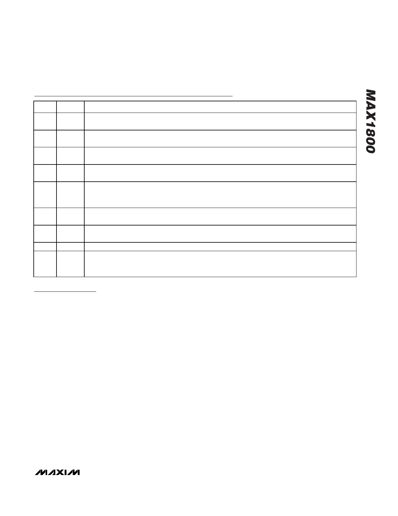
Pin Description (continued)
PIN NAME
FUNCTION
24
ONM
Main Converter Enable Input. High level turns the main converter on. Connect ONM to POUT to automatically
start the main converter. When the main converter is off, all other outputs are disabled.
25
AI
Analog Gain Block Input. AI is the positive input to the gain block. The negative input is internally connected
to the 1.25V reference.
26
AO
Analog Gain Block Output. AO is a push-pull output driven between GND and POUT. The voltage gain of the
block is approximately 100.
27
ONA
Analog Gain Block Enable Input. Connect ONA to POUT to enable the gain block. When ONA is low, the AO
output is driven to POUT.
Maximum Duty-Cycle Control Input for Auxiliary Controller 3. Connect to POUT to set the default maximum
28 DCON3 duty cycle. Connect a resistive voltage-divider from REF to DCON3 to set the maximum duty cycle between
40% and 90%. Pull DCON3 below 400mV to turn the controller off.
29
COMP3
Compensation for Auxiliary Controller 3. Output of transconductance error amplifier. Connect a series resistor
and capacitor to GND to compensate the control loop. See Compensation Design.
Feedback Input for Auxiliary Controller 3. Connect a feedback resistive voltage-divider from the output to FB3
30
FB3
to set the output voltage. Regulation voltage is VREF (1.25V).
31
ON3 Enable Input for Auxiliary Controller 3. Connect ON2 to POUT to automatically start auxiliary controller 3.
External MOSFET Gate Drive Output for Auxiliary Controller 3. DL3 swings between POUT and GND with
32
DL3 typical 500mA drive current. Connect DL3 to the gate of the external switching N-channel MOSFET for
auxiliary controller 3.
Detailed Description
The MAX1800 typical application circuit is shown in
Figure 1. It features a main step-up DC-DC converter,
three auxiliary step-up DC-DC controllers, an uncom-
mitted gain block, a power-ready comparator, and con-
trol capability for multiple external MAX1801 slave
DC-DC controllers. The uncommitted gain block can be
used with an external P-Channel MOSFET to make a
linear regulator. The linear regulator can be used with
the main output for step-up/step-down functionality or
to make a separate stand-alone output voltage.
Together, these provide a complete high-efficiency
power-supply solution for digital still cameras. Figure 2
shows the MAX1800 functional diagram.
Master-Slave Configuration
The MAX1800 supports MAX1801 “slave” controllers
that obtain input power, a voltage reference, and an
oscillator signal directly from the MAX1800 “master”
DC-DC converter. The master-slave configuration
reduces system cost by eliminating redundant circuitry
and controlling the harmonic content of noise with syn-
chronized converter switching.
Main DC-DC Converter
The MAX1800 main step-up DC-DC switching convert-
er generates a 2.7V to 5.5V output voltage from a +0.7V
to +5.5V battery input voltage. An internal switch and
synchronous rectifier allow conversion efficiencies as
high as 95% while reducing both circuit size and the
number of external components. The converter oper-
ates in a low-noise, constant-frequency PWM mode to
regulate the voltage across the load. Switching har-
monics generated by fixed-frequency operation are
consistent and easily filtered.
The internal N-channel MOSFET switch turns on during
the first part of each cycle, allowing current to ramp up
in the inductor and store energy in a magnetic field.
During the second part of each cycle, the MOSFET
turns off and the voltage across the inductor reverses,
forcing current through the internal P-channel synchro-
nous rectifier to the output filter capacitor and load. As
the energy stored in the inductor is depleted, the cur-
rent ramps down. The synchronous rectifier turns off
when the inductor current approaches zero or at the
beginning of a cycle.
The current-mode PWM controller uses the voltage at
COMPM to program the inductor current and regulate
_______________________________________________________________________________________ 9
Share Link: 