MAX3349EA 查看數據表(PDF) - Maxim Integrated
零件编号
产品描述 (功能)
生产厂家
MAX3349EA Datasheet PDF : 17 Pages
| |||
USB 2.0 Full-Speed Transceiver with UART
Multiplexing Mode
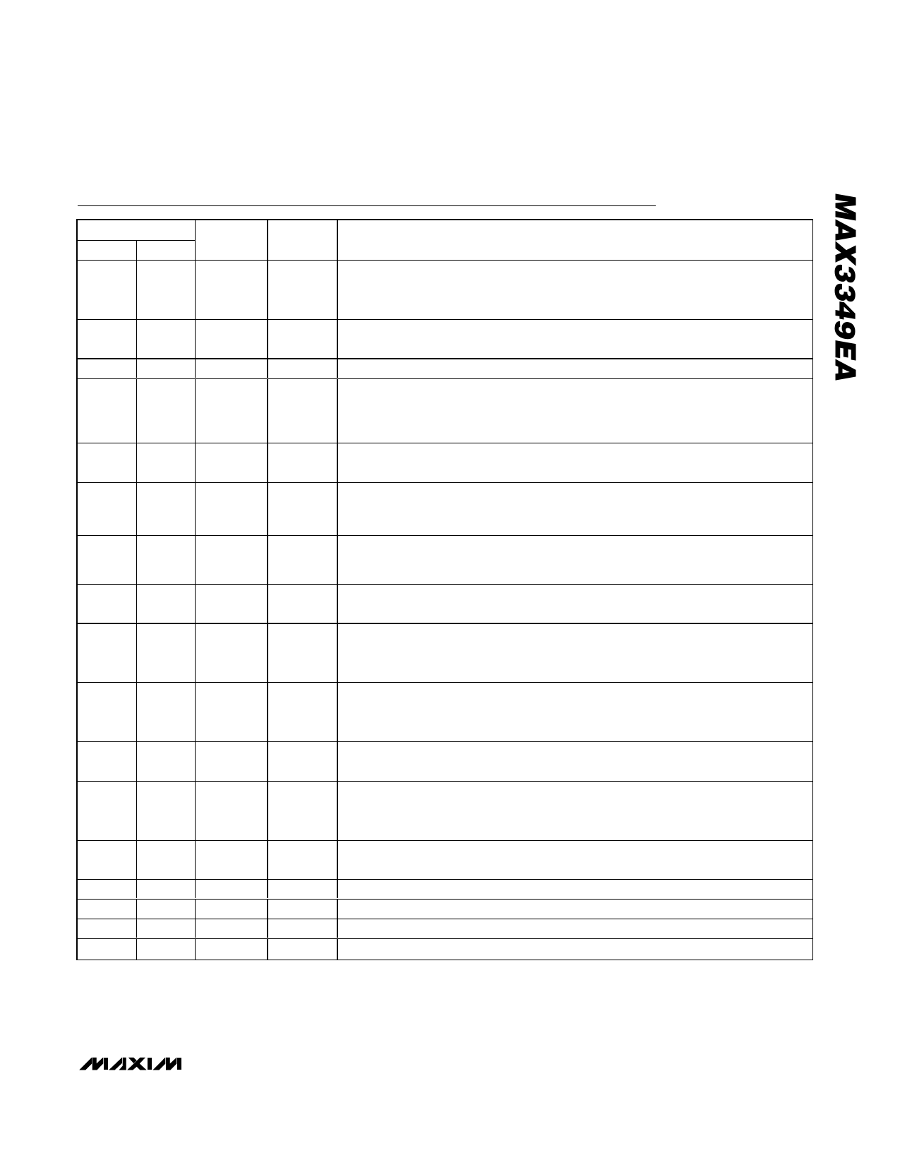
PIN
UCSP TQFN
TYPE
A1
1
POWER
A2
2
OUTPUT
A3
3
INPUT
A4
4
OUTPUT
B1
15
POWER
B2
16
I/O
B3
5
I/O
B4
6
OUTPUT
C1
14
POWER
C2
13
INPUT
C3
8
INPUT
C4
7
INPUT
D1
12
POWER
D2
11
I/O
D3
10
I/O
D4
9
POWER
—
EP
—
Pin Description
NAME
FUNCTION
VUART
RX
TX
BD
VL
VM
VP
RCV
VTRM
ENUM
SUS
OE
VBUS
D+
D-
GND
EP
UART Supply Voltage. VUART powers the internal UART transmitter and receiver.
Connect a regulated voltage between +2.7V and +3.3V to VUART. Bypass VUART to
GND with a 0.1µF ceramic capacitor.
UART Receive Output. In UART mode, RX is a level-shifted output that expresses
the logic state of D+.
UART Transmit Input. In UART mode, D- follows the logic state on TX.
USB Detect Output. When VBUS exceeds the VTH-BUS threshold, BD is logic-high to
indicate that the MAX3349E is connected to a USB host. The MAX3349E operates in
USB mode when BD is logic-high, and operates in UART mode when BD is logic-
low.
Digital Logic Supply. Connect a +1.4V to +2.75V supply to VL. Bypass VL to GND
with a 0.1µF or larger ceramic capacitor.
Receiver Output/Driver Input. VM functions as a receiver output when OE = VL. VM
follows the logic state of D- when receiving. VM functions as a driver input when OE
= GND (Tables 2 and 3).
Receiver Output/Driver Input. VP functions as a receiver output when OE = VL. VP
follows the logic state of D+ when receiving. VP functions as a driver input when OE
= GND (Tables 2 and 3).
Differential Receiver Output. In USB mode, RCV is the output of the USB differential
receiver (Table 3).
Internal Regulator Output. VTRM provides a regulated +3.3V output. Bypass VTRM to
GND with a 1µF ceramic capacitor. VTRM draws power from VBUS. Do not power
external circuitry from VTRM.
Enumerate Input. Drive ENUM to VL to connect the internal 1.5kΩ resistor from D+ to
VTRM (when VBUS is present). Drive ENUM to GND to disconnect the internal 1.5kΩ
pullup resistor. ENUM has no effect when the device is in UART mode.
Suspend Input. Drive SUS low for normal operation. Drive SUS high to force the
MAX3349E into suspend mode.
Output Enable. Drive OE low to set VP/VM to transmitter inputs in USB mode. Drive
OE high to set VP/VM to receiver outputs in USB mode. OE has no effect when the
device is in UART mode.
USB Supply Voltage. VBUS provides power to the internal linear regulator when in
USB mode. Bypass VBUS to GND with a 0.1µF ceramic capacitor.
USB Differential Data Input/Output. Connect D+ directly to the USB connector.
USB Differential Data Input/Output. Connect D- directly to the USB connector.
Ground
Exposed Paddle. Connect exposed paddle to GND.
_______________________________________________________________________________________ 7
Share Link: 