MAX5021 查看數據表(PDF) - Maxim Integrated
零件编号
产品描述 (功能)
生产厂家
MAX5021 Datasheet PDF : 11 Pages
| |||
Current-Mode PWM Controllers for Isolated
Power Supplies
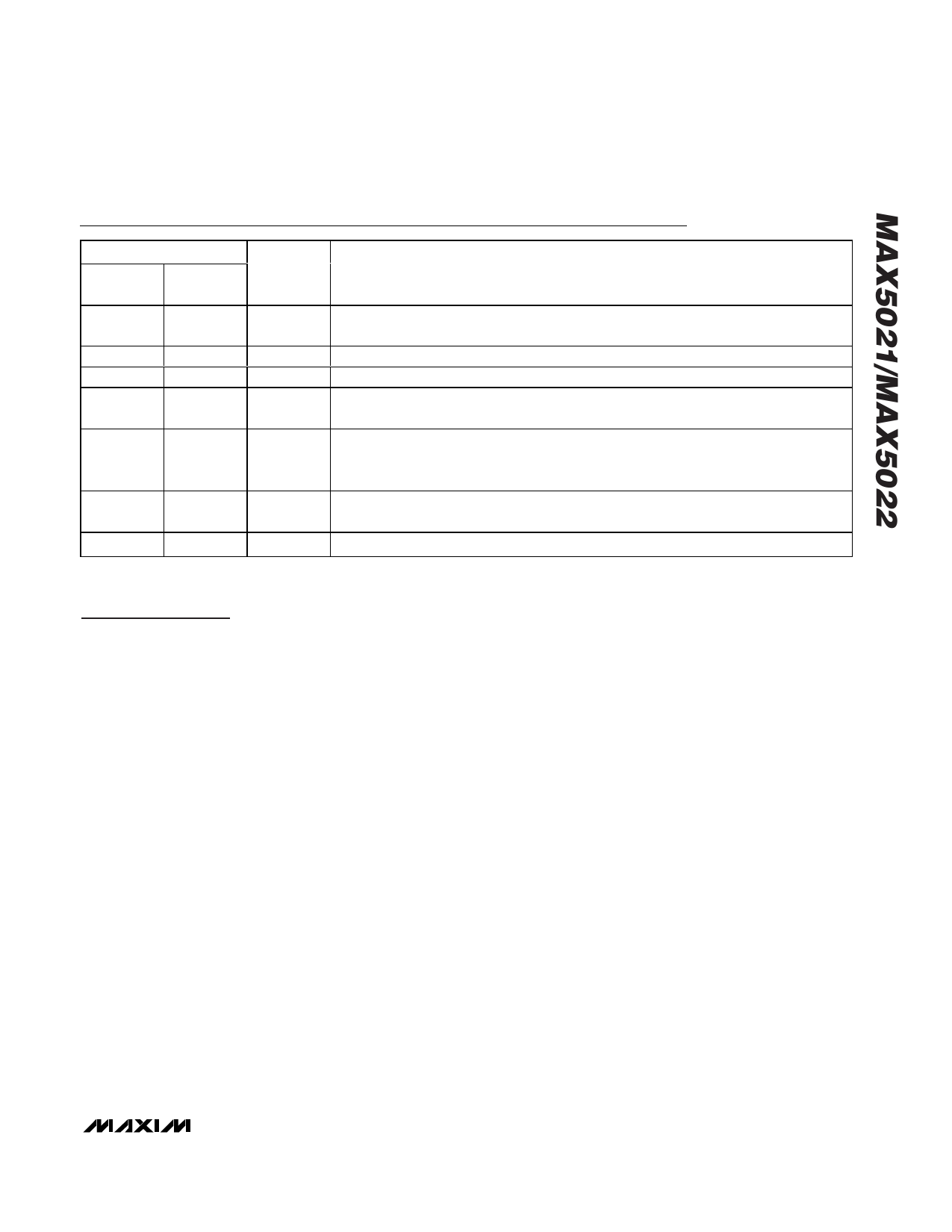
PIN
SOT23
PDIP
µMAX
1
8
2
7
3
6
4
3
5
2
6
1
—
4, 5
Pin Description
NAME
FUNCTION
CS
GND
NDRV
VCC
VIN
OPTO
N.C.
Current Sense Connection for PWM Regulation and Overcurrent Protection. The current-limit
comparator threshold is internally set to 0.6V.
Power-Supply Ground
External N-Channel MOSFET Gate Connection
Gate Drive Supply. Internally regulated down from VIN. Decouple with a 10nF or larger
capacitor to GND.
IC Supply. Decouple with a 10nF or larger capacitor to GND. Connect a startup resistor
(Rs) from the input supply line to VIN. Connect to bias winding through diode rectifier.
See Typical Operating Circuit.
Optocoupler Transistor Collector Connection. Connect emitter of optocoupler to GND.
The OPTO has an internal pullup resistor with a typical value of 6.2kΩ.
No Connection. Do not make connections to these pins.
Detailed Description
The MAX5021/MAX5022 are current-mode PWM con-
trollers that have been specifically designed for use in
isolated power supplies. An undervoltage lockout cir-
cuit (UVLO) with a large hysteresis (14V) along with
very low startup and operating current result in high-
efficiency, universal input power supplies. Both devices
can be used in power supplies capable of operating
from a universal 85VAC to 265VAC line or the telecom
voltage range of -36VDC to -72VDC.
Power supplies designed with these devices use a
high-value startup resistor, RS, (series combination of
R1 and R2) that charges a reservoir capacitor, C2 (see
Figure 1). During this initial period while the voltage is
less than the UVLO start threshold, the IC typically con-
sumes only 50µA of quiescent current. This low startup
current and the large UVLO hysteresis combined with
the use of a ceramic capacitor C2 keeps the power dis-
sipation in RS to less than 1/4W even at the high end of
the universal AC input voltage (265VAC).
The MAX5021/MAX5022 include a cycle-by-cycle cur-
rent limit which turns off the gate drive to the external
MOSFET during an overcurrent condition. If the output
on the secondary side of transformer T1 is shorted, the
tertiary winding voltage will drop below the 10V thresh-
old causing the UVLO circuit to turn off the gate drive to
the external power MOSFET, thus re-initiating the start-
up sequence.
Startup
Figure 2 shows the voltages on VIN and VCC during
startup. Initially, both VIN and VCC are 0V. After the line
voltage is applied, C2 charges through the startup
resistor, RS, to an intermediate voltage at which point
the internal reference and regulator begin charging C3
(see Figure 1). The bias current consumed by the
device during this period is only 50µA; the remaining
input current charges C2 and C3. Charging of C3 stops
when the VCC voltage reaches approximately 9.5V,
while the voltage across C2 continues rising until it
reaches the wakeup level of 24V. Once VIN exceeds
the UVLO threshold, NDRV begins switching the
MOSFET, transferring energy to the secondary and ter-
tiary outputs. If the voltage on the tertiary output builds
to higher than 10V (UVLO lower threshold), then startup
has been accomplished and sustained operation
will commence.
If VIN drops below 10V before startup is complete, then
the IC goes back into UVLO. In this case, increase the
value of C2 and/or use a MOSFET with a lower gate-
charge requirement.
Startup Time Considerations
The VIN bypass capacitor C2 supplies current immediate-
ly after wakeup. The size of C2 will determine the number
of cycles available for startup. Large values for C2 will
increase the startup time, but will also supply more gate
charge, allowing for more cycles after wakeup. If the
value of C2 is too small, VIN will drop below 10V because
_______________________________________________________________________________________ 5
Share Link: 