MAX5422 查看數據表(PDF) - Maxim Integrated
零件编号
产品描述 (功能)
生产厂家
MAX5422 Datasheet PDF : 11 Pages
| |||
256-Tap, Nonvolatile, SPI-Interface,
Digital Potentiometers
Programmable Filter
Figure 5 shows the configuration for a 1st-order pro-
grammable filter. The gain of the filter is adjusted by
R2, and the cutoff frequency is adjusted by R3. Use the
following equations to calculate the DC gain (G) and
the 3dB cutoff frequency (fC):
G = 1 + R1
R2
fC
=
2π ×
1
R3 ×
C
C
VIN
H
VOUT
R3
W
R1
L
H
MAX5422
MAX5423
MAX5424
R2
W
L
Figure 5. Programmable Filter
Adjustable Voltage Reference
Figure 6 shows the MAX5422/MAX5423/MAX5424 used
as the feedback resistors in an adjustable voltage-ref-
erence application. Independently adjust the output
voltage of the MAX6160 from 1.23V to VIN - 0.2V by
changing the wiper position of the MAX5422/
MAX5423/MAX5424.
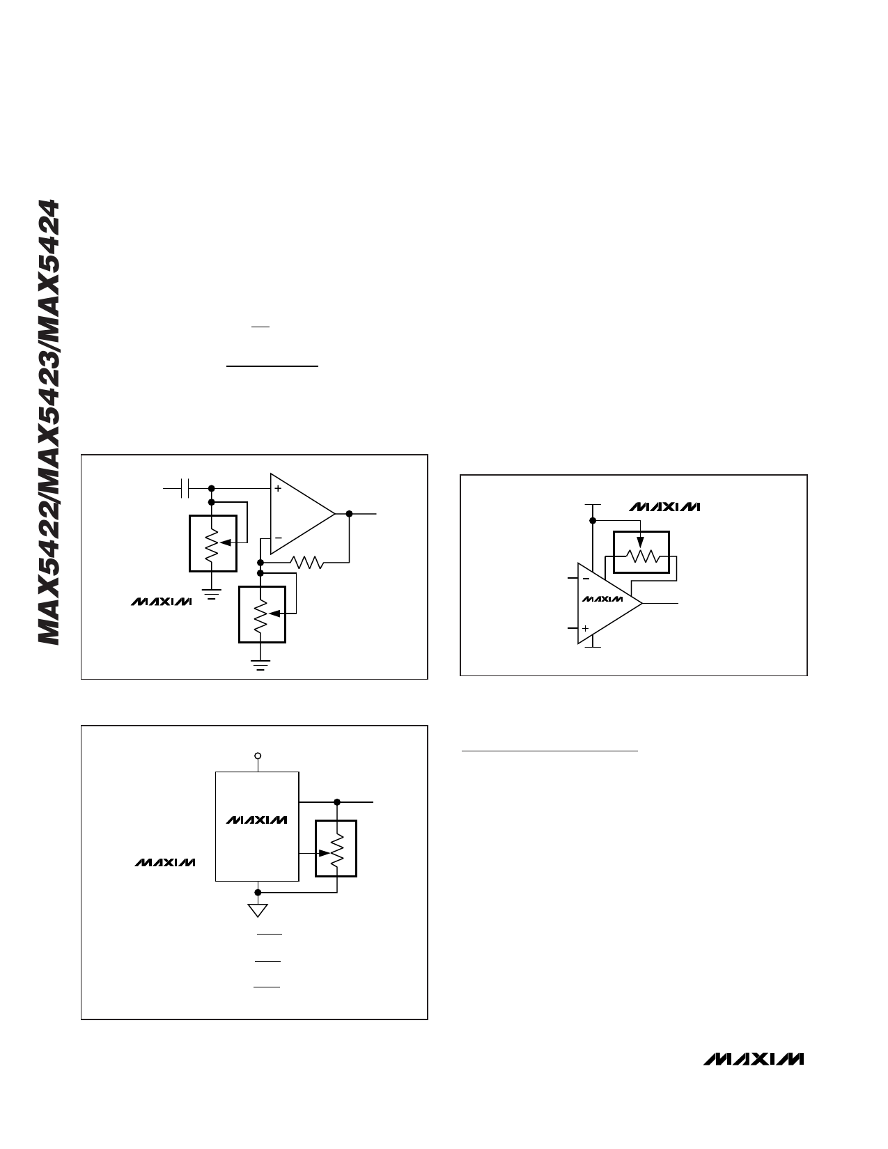
Offset Voltage and Gain Adjustment
Connect the high and low terminals of one potentiome-
ter of a MAX5422/MAX5423/MAX5424 between the
NULL inputs of a MAX410 and the wiper to the op
amp’s positive supply to nullify the offset voltage over
the operating temperature range. Install another
MAX5422/MAX5423/MAX5424 potentiometer in the
feedback path to adjust the gain of the MAX410 (see
Figure 7).
5V
MAX5422
7
21
8
6
MAX410
3
4
-5V
Figure 7. Offset Voltage Adjustment Circuit
+5V
MAX5422
MAX5423
MAX5424
VIN
OUT
MAX6160
ADJ W
GND
V0 REF
H
L
V0
=
1.23V
50kΩ
R2(kΩ)
FOR
THE
MAX5422
V0 = 1.23V
100kΩ
R2(kΩ)
FOR
THE
MAX5423
V0 = 1.23V
200kΩ
R2(kΩ)
FOR
THE
MAX5424
Chip Information
TRANSISTOR COUNT: 10,191
PROCESS: BiCMOS
Figure 6. Adjustable Voltage Reference
10 ______________________________________________________________________________________
Share Link: 