MAX5422 查看數據表(PDF) - Maxim Integrated
零件编号
产品描述 (功能)
生产厂家
MAX5422 Datasheet PDF : 11 Pages
| |||
256-Tap, Nonvolatile, SPI-Interface,
Digital Potentiometers
Write Wiper Register
Data written to this register (C1, C0 = 00) controls the
wiper positions. The 8 data bits (D7 to D0) indicate the
position of the wiper. For example, if DIN = 0000 0000,
the wiper moves to the position closest to L. If DIN =
1111 1111, the wiper moves closest to H.
This command writes data to the volatile random
access memory (RAM), leaving the NV registers
unchanged. When the device powers up, the data
stored in the NV registers transfers to the volatile wiper
register, moving the wiper to the stored position.
Write NV Register
The “write NV register” command (C1, C0 = 01) stores
the position of the wipers to the NV registers for use at
power-up. Alternatively, the “copy wiper register to NV
register” command writes to the NV register. Writing to the
NV registers, does not affect the position of the wipers.
Copy Wiper Register to NV Register
The “copy wiper register to NV register” command (C1,
C0 = 10) stores the current position of the wiper to the
NV register for use at power-up.
Copy NV Register to Wiper Register
The “copy NV register to wiper register” (C1, C0 = 11)
restores the wiper position to the current value stored in
the NV register.
Standby Mode
The MAX5422/MAX5423/MAX5424 feature a low-power
standby mode. When the device is not being pro-
grammed, it enters into standby mode and supply cur-
rent drops to 0.5µA (typ).
Nonvolatile Memory
The internal EEPROM consists of a nonvolatile register
that retains the last value stored prior to power-down.
The nonvolatile register is programmed to midscale at
the factory. The nonvolatile memory is guaranteed for
50 years for wiper data retention and up to 200,000
wiper write cycles.
Power-Up
Upon power-up, the MAX5422/MAX5423/MAX5424
load the data stored in the nonvolatile wiper register
into the volatile wiper register, updating the wiper posi-
tion with the data stored in the nonvolatile wiper regis-
ter. This initialization period takes 10µs.
Applications Information
The MAX5422/MAX5423/MAX5424 are intended for cir-
cuits requiring digitally controlled adjustable resis-
tance, such as LCD contrast control (where voltage
biasing adjusts the display contrast), or programmable
filters with adjustable gain and/or cutoff frequency.
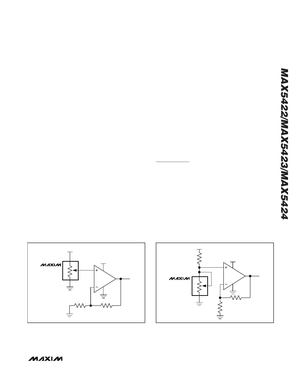
Positive LCD Bias Control
Figures 3 and 4 show an application where a voltage-
divider or variable resistor is used to make an
adjustable, positive LCD-bias voltage. The op amp pro-
vides buffering and gain to the resistor-divider network
made by the potentiometer (Figure 3) or to a fixed
resistor and a variable resistor (see Figure 4).
MAX5422
MAX5423
MAX5424
5V
H
W
L
30V
VOUT
5V
H
MAX5422
MAX5423
W
MAX5424
L
30V
VOUT
Figure 3. Positive LCD-Bias Control Using a Voltage-Divider
Figure 4. Positive LCD-Bias Control Using a Variable Resistor
_______________________________________________________________________________________ 9
Share Link: 