MAX6336US17D1-T(1998) жҹҘзңӢж•ёж“ҡиЎЁпјҲPDFпјү - Maxim Integrated
йӣ¶д»¶зј–еҸ·
дә§е“ҒжҸҸиҝ° (еҠҹиғҪ)
з”ҹдә§еҺӮ家
MAX6336US17D1-T
(Rev.:1998)
(Rev.:1998)
Maxim Integrated

MAX6336US17D1-T Datasheet PDF : 8 Pages
| |||
4-Pin, Ultra-Low-Voltage, Low-Power
ВөP Reset Circuits with Manual Reset
Pin Description
PIN
MAX6335
1
MAX6336
MAX6337
1
вҖ”
2
2
вҖ”
3
3
4
4
NAME
GND
RESET
RESET
MR
VCC
FUNCTION
Ground
Active-Low Reset Output. RESET remains low while VCC is below the reset
threshold, or MR is asserted and for a reset timeout period (tRP) after VCC
rises above the reset threshold, or MR is deasserted. RESET on the
MAX6337 is open-drain.
Active-High Reset Output. RESET remains high while VCC is below the
reset threshold, or MR is asserted and for a reset timeout period (tRP) after
VCC rises above the reset threshold, or MR is deasserted. RESET also
asserts when MR is low.
Manual-Reset Input. A logic low on MR asserts reset. Reset remains
asserted as long as MR is low, and for the reset timeout period (tRP) after
MR goes high. Leave unconnected or connect to VCC if not used.
Supply Voltage (0.7V to 5.5V)
Applications Information
Manual-Reset Inputs
Many ВөP-based products require manual-reset capabil-
ity, allowing the operator, a test technician, or external
logic circuitry to initiate a reset. A logic low on MR
asserts reset. Reset remains asserted while MR is low,
and for the reset active timeout period after MR returns
high. MR has an internal 20kв„Ұ pull-up resistor, so it can
be left unconnected if not used. Connect a normally
open momentary switch from MR to GND to create a
manual-reset function; external debounce circuitry is
not required.
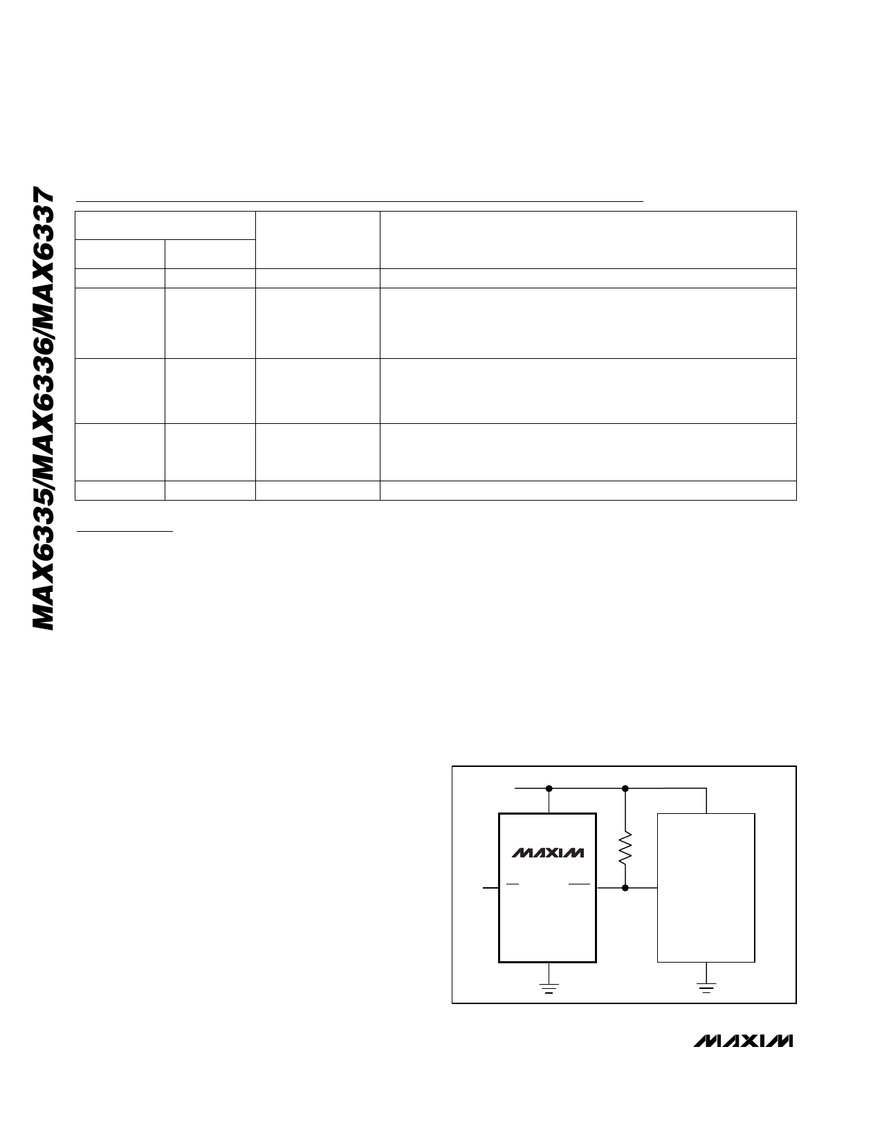
Interfacing to ВөPs with
Bidirectional Reset Pins
Since the RESET output on the MAX6337 is open-drain,
this device interfaces easily with ВөPs that have bidirec-
tional reset pins, such as the Motorola 68HC11.
Connecting the ВөP supervisorвҖҷs RESET output directly
to the microcontrollerвҖҷs (ВөCвҖҷs) RESET pin with a single
pull-up resistor allows either device to assert reset
(Figure 1).
Negative-Going VCC Transients
In addition to issuing a reset to the ВөP during power-up,
power-down, and brownout conditions, these devices
are relatively immune to short-duration, negative-going
VCC transients (glitches). The Typical Operating
Characteristics show the Maximum Transient Duration
vs. Reset Comparator Overdrive graph. The graph
shows the maximum pulse width that a negative-going
VCC transient may typically have without issuing a reset
signal. As the amplitude of the transient increases, the
maximum allowable pulse width decreases.
Ensuring a Valid Reset Output
down to VCC = 0
When VCC falls below 1V and approaches the minimum
operating voltage of 0.7V, push/pull-structured reset
sinking (or sourcing) capabilities decrease drastically.
High-impedance CMOS-logic inputs connected to the
RESET pin can drift to indeterminate voltages. This
does not present a problem in most cases, since most
ВөPs and circuitry do not operate at VCC below 1V. For
the MAX6336, where RESET must be valid down to 0,
adding a pull-down resistor between RESET and GND
removes stray leakage currents, holding RESET low
VCC
VCC
MAX6337
MR
RESET
VCC
ВөP
MOTOROLA
68HCXX
RESET
INPUT
GND
GND
Figure 1. Interfacing to ВөPs with Bidirectional Reset Pins
4 _______________________________________________________________________________________
Share Link: