MAX6900 查看數據表(PDF) - Maxim Integrated
零件编号
产品描述 (功能)
生产厂家
MAX6900 Datasheet PDF : 17 Pages
| |||
I2C-Compatible RTC in a TDFN
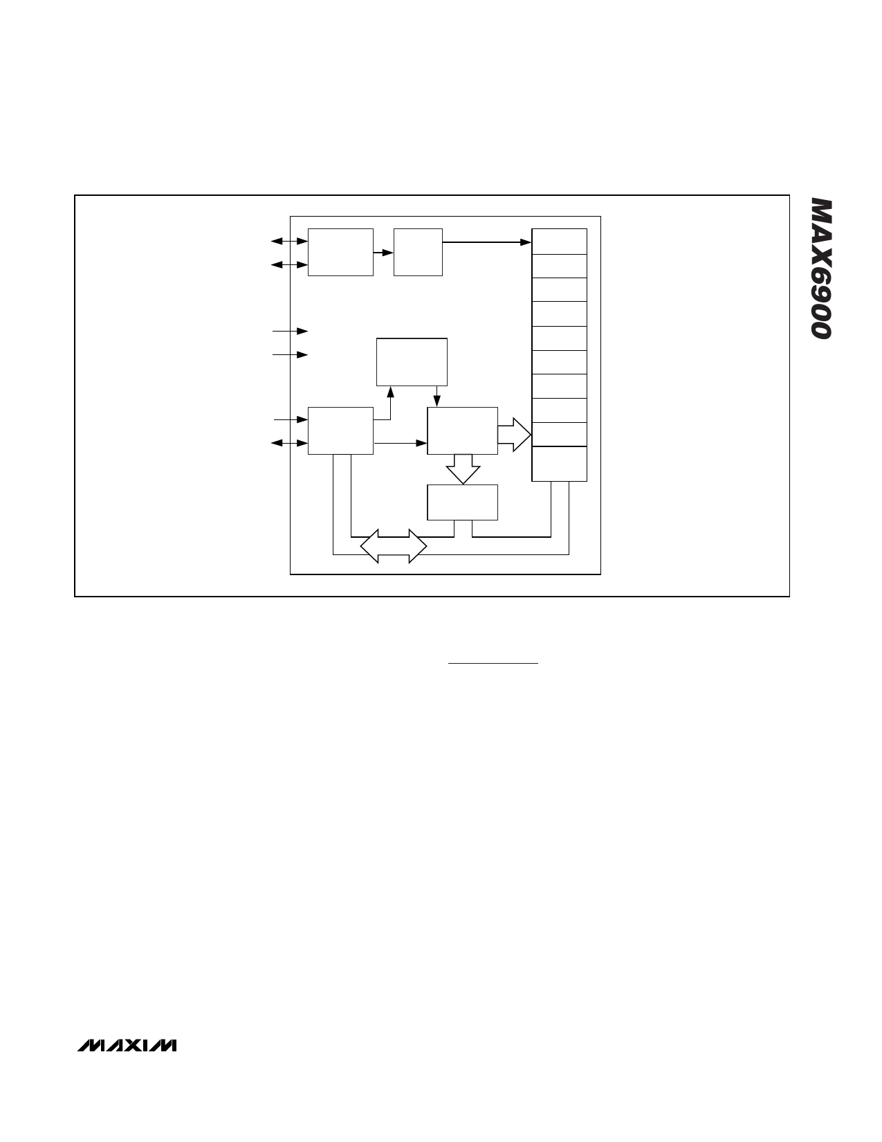
X1
X2
1Hz
OSCILLATOR
32.768kHz
DIVIDER
VCC
GND
CONTROL
LOGIC
SCL
I2C BUS
SDA
INTERFACE
ADDRESS
REGISTER
31 X 8
SRAM
SECONDS
MINUTES
HOURS
DATE
MONTH
DAY
YEAR
CONTROL
CENTURY
CLOCK
BURST
Figure 2. Functional Diagram
days, including corrections for leap year up to the year
2100.
Crystal Oscillator
The MAX6900 uses an external, standard 12.5pF load
watch crystal. No other external components are
required for this timekeeping oscillator. Power-up oscil-
lator start-time is dependent mainly upon applied VCC
and ambient temperature. The MAX6900, because of
its low timekeeping current, exhibits a typical startup
time between 5s to 10s.
I2C-Compatible Interface
Interfacing the MAX6900 with a microprocessor or
other I2C master is made easier by using the serial, I2C-
bus-compatible or other I2C master interface. Only 2
wires are required to communicate with the clock and
SRAM: SCL (serial clock) and SDA (data line). Data is
transferred to and from the MAX6900 over the I/O data
line, SDA. The MAX6900 uses 7-bit slave ID address-
ing. The MAX6900 does not respond to general call
address commands.
Applications Information
I2C-Bus-Compatible Interface
The I2C-bus-compatible serial interface allows bidirec-
tional, 2-wire communication between multiple ICs. The
two lines are SDA and SCL. Connect both lines to a
positive supply through individual pullup resistors. A
device on the I2C-compatible bus that generates a
message is called a transmitter and a device that
receives the message is a receiver. The device that
controls the message is the master and the devices
that are controlled by the master are called slaves
(Figure 3). The word message refers to data in the form
of three 8-bit bytes for a Single Read or Write. The first
byte is the Slave ID byte, the second byte is the
Address/Command byte, and the third is the data.
Data transfer can only be initiated when the bus is not
busy (both SDA and SCL are high). A high-to-low tran-
sition of SDA while SCL is high is defined as the Start
(S) condition; low-to-high transition of the data line
while SCL is high is defined as the Stop (P) condition
(Figure 4).
_______________________________________________________________________________________ 5
Share Link: 