MAX6900 查看數據表(PDF) - Maxim Integrated
零件编号
产品描述 (功能)
生产厂家
MAX6900 Datasheet PDF : 17 Pages
| |||
I2C-Compatible RTC in a TDFN
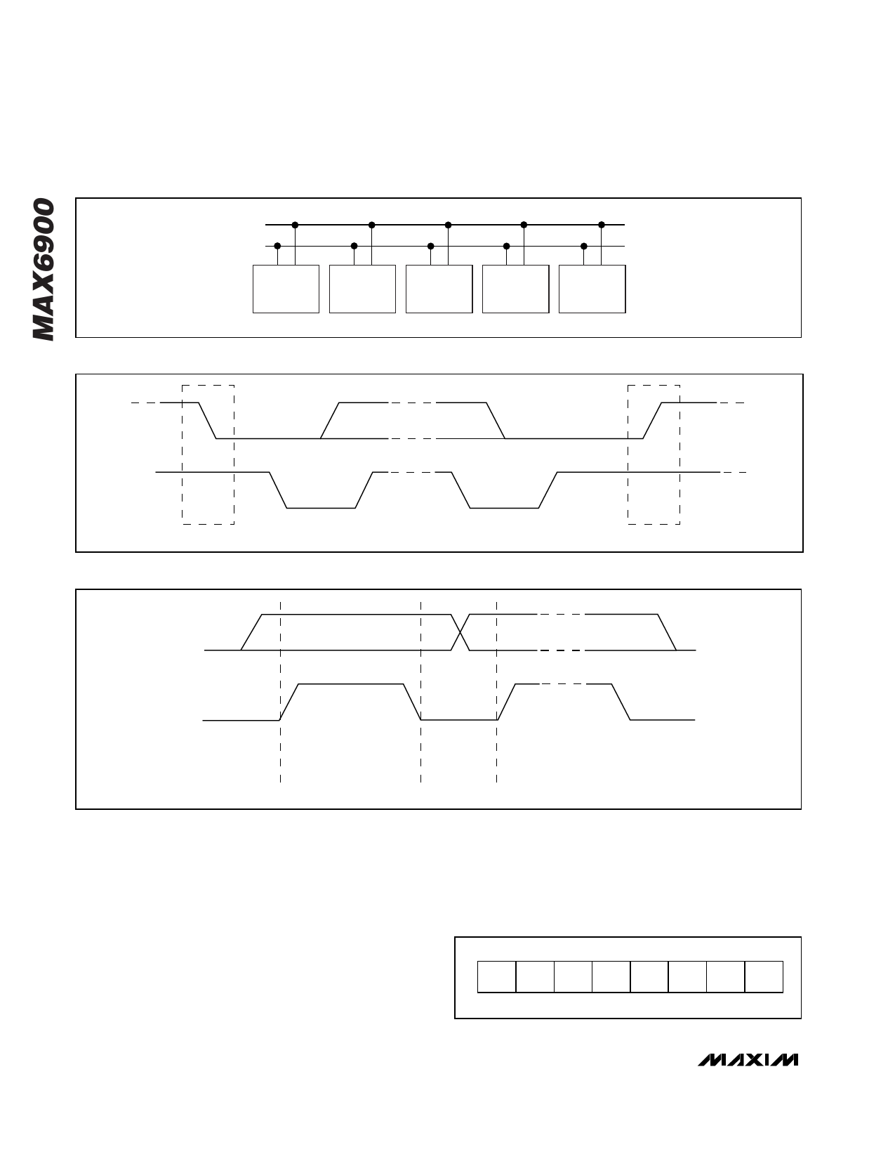
SDA
SCL
MASTER
TRANSMITTER/
RECEIVER
SLAVE
RECEIVER
SLAVE
TRANSMITTER/
RECEIVER
MASTER
TRANSMITTER
MASTER
TRANSMITTER/
RECEIVER
Figure 3. I2C Bus System Configuration
SDA
SDA
SCL
S
START CONDITION
Figure 4. I2C Bus Start and Stop Conditions
SCL
P
STOP CONDITION
SDA
SCL
DATA LINE
STABLE;
DATA VALID
CHANGE
OF DATA
ALLOWED
Figure 5. I2C Bus Bit Transfer
After the Start condition occurs, 1 bit of data is trans-
ferred for each clock pulse. The data on SDA must
remain stable during the high portion of the clock pulse
as changes in data during this time are interpreted as a
control signal (Figure 5). Any time a start condition
occurs, the Slave ID must follow immediately, regard-
less of completion of the previous data transfer.
Before any data is transmitted on the I2C-bus-compati-
ble serial interface, the device that is expected to
respond is addressed first. The first byte sent after the
start (S) procedure is the Address byte or 7-bit Slave
ID. The MAX6900 acts as a slave transmitter/receiver.
Therefore, SCL is only an input clock signal and SDA is
a bidirectional data line. The Slave Address for the
MAX6900 is shown in Figure 6.
1
0
1
0
0
0
0 RD/W
BIT 7
BIT 0
Figure 6. I2C Bus Slave Address or 7-Bit Slave ID
6 _______________________________________________________________________________________
Share Link: 