MAX7036(2010) 查看數據表(PDF) - Maxim Integrated
零件编号
产品描述 (功能)
生产厂家
MAX7036 Datasheet PDF : 13 Pages
| |||
300MHz to 450MHz ASK Receiver
with Internal IF Filter
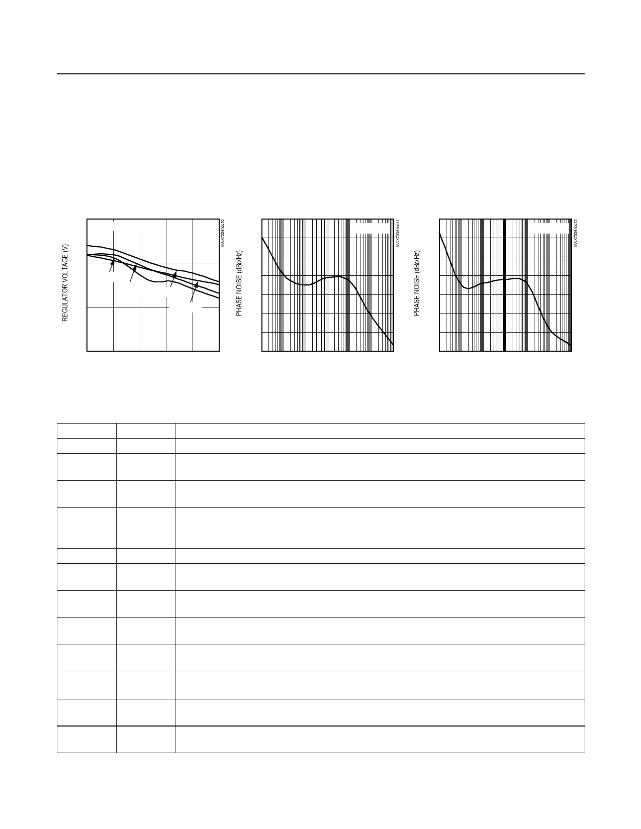
Typical Operating Characteristics (continued)
(Typical Application Circuit, VAVDD = VDD = VDVDD = 3.3V, fRF = 315MHz, TA = +25°C, unless otherwise noted.)
REGULATOR VOLTAGE
vs. REGULATOR CURRENT
3.15
VDD = 5V, +5V CIRCUIT
PHASE NOISE
vs. OFFSET FREQUENCY
-50
fRF = 315MHz
-60
PHASE NOISE
vs. OFFSET FREQUENCY
-50
fRF = 433MHz
-60
-70
-70
3.10
TA = +105°C
-80
-80
TA = +85°C TA = +25°C
-90
-90
3.05
TA = -40°C
-100
-100
-110
-110
3.00
0
5
10
15
20
25
REGULATOR CURRENT (mA)
-120
0.01
0.1 1 10 100 1000 10,000
OFFSET FREQUENCY (kHz)
-120
0.01
0.1 1 10 100 1000 10,000
OFFSET FREQUENCY (kHz)
Pin Description
PIN
NAME
FUNCTION
1
ENABLE Enable Input. Internally pulled down to ground. Set VENABLE = VDD for normal operation.
2
XTAL2
Crystal Input 2. Connect an external crystal from XTAL2 to XTAL1. Bypass to GND if XTAL1 is driven
from an AC-coupled external reference (see the Crystal Oscillator section).
3
XTAL1
Crystal Input 1. Connect an external crystal from XTAL2 to XTAL1. Can also be driven with an AC-
coupled external reference oscillator (see the Crystal Oscillator section).
Positive Analog Supply Voltage. Connect to DVDD. Bypass to GND with a 0.1μF capacitor as close as
4
AVDD possible to the device (see the Typical Application Circuit). For 5.0V operation, AVDD is internally
connected to an on-chip 3.2V LDO regulator. For 3.3V operation, connect AVDD to VDD.
5
LNAIN Low-Noise Amplifier Input. Must be AC-coupled (see the Low-Noise Amplifier section).
6
LNAOUT
Low-Noise Amplifier Output. Must be connected to AVDD through a parallel LC tank circuit. AC-
couple to MIXIN2 (see the Low-Noise Amplifier section).
7
MIXIN2
2nd Differential Mixer Input. Connect to the LNAOUT side of the LC tank filter through a 100pF
capacitor (see the Typical Application Circuit).
8
MIXIN1 1st Differential Mixer Input. Connect to the AVDD side of the LC tank filter through a 100pF capacitor
(see the Typical Application Circuit).
9
IFC2
IF Filter Capacitor Connection 2. This is for the Sallen-Key IF filter. Connect a capacitor from IFC2 to GND.
The value of the capacitor is determined by the IF filter bandwidth (see the Typical Application Circuit).
10
IFC1
IF Filter Capacitor Connection 1. This is for the Sallen-Key IF filter. Connect a capacitor from IFC1 to IFC3.
The value of the capacitor is determined by the IF filter bandwidth (see the Typical Application Circuit).
11
IFC3
IF Filter Capacitor Connection 3. This is for the Sallen-Key IF filter. Connect a capacitor from IFC3 to IFC1.
The value of the capacitor is determined by the IF filter bandwidth (see the Typical Application Circuit).
12
DVDD
Positive Digital Supply Voltage Input. Connect to AVDD. Bypass to GND with a 0.01μF capacitor as
close as possible to the device (see the Typical Application Circuit).
6 _______________________________________________________________________________________
Share Link: 