MAX8643 查看數據表(PDF) - Maxim Integrated
零件编号
产品描述 (功能)
生产厂家
MAX8643 Datasheet PDF : 16 Pages
| |||
3A, 2MHz Step-Down Regulator
with Integrated Switches
Current Limit
The internal, high-side MOSFET has a typical 5.5A
peak current-limit threshold. When current flowing out
of LX exceeds this limit, the high-side MOSFET turns off
and the synchronous rectifier turns on. The synchro-
nous rectifier remains on until the inductor current falls
below the low-side current limit. This lowers the duty
cycle and causes the output voltage to droop until the
current limit is no longer exceeded. The MAX8643 uses
a hiccup mode to prevent overheating during short-cir-
cuit output conditions.
During current limit if VFB drops below 420mV and
stays below this level for 12µs or more, the part enters
hiccup mode. The high-side MOSFET and the synchro-
nous rectifier are turned off and both COMP and REFIN
are internally pulled low. If REFIN and SS are connect-
ed together, then both are pulled low. The part remains
in this state for 1024 clock cycles and then attempts to
restart for 128 clock cycles. If the fault-causing current
limit has cleared, the part resumes normal operation.
Otherwise, the part reenters hiccup mode again.
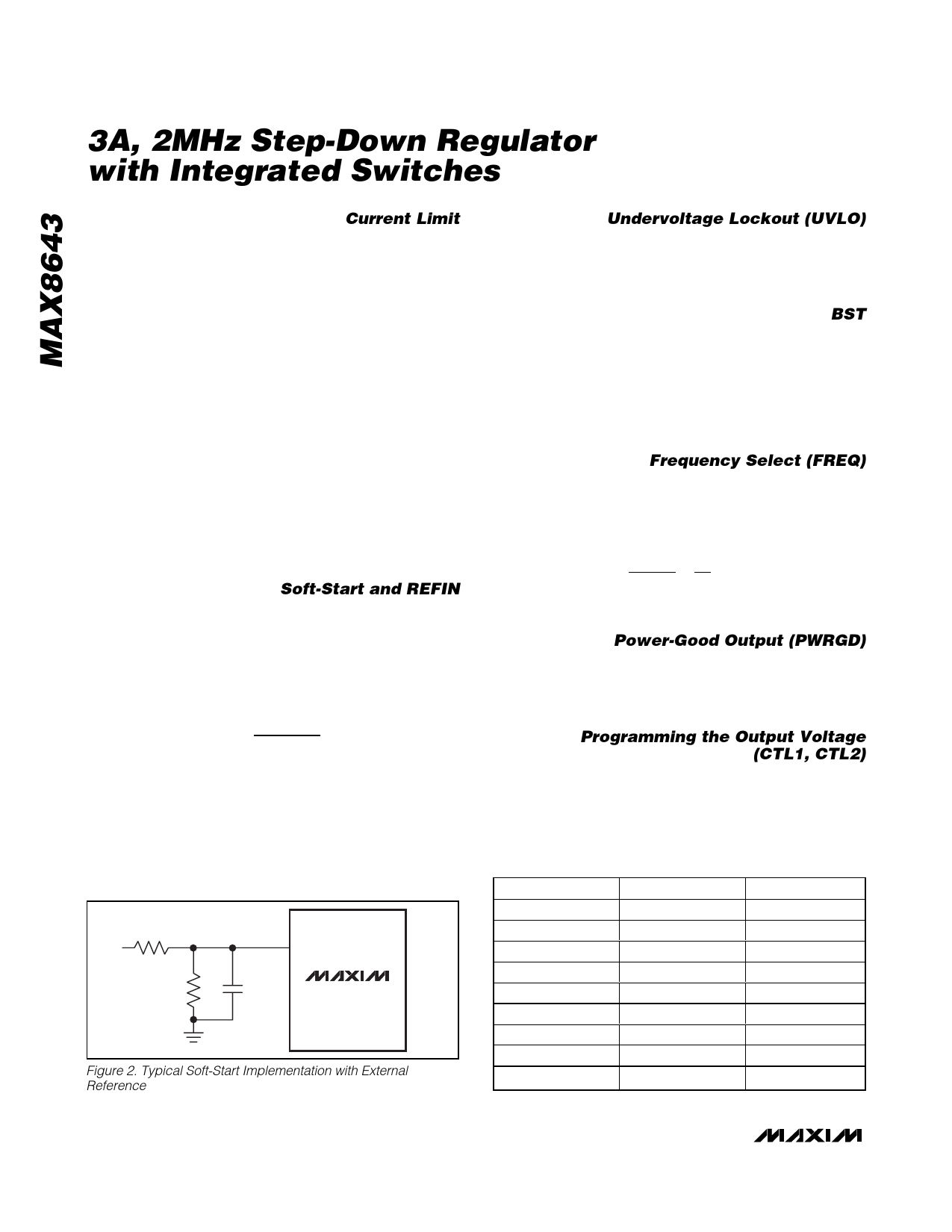
Soft-Start and REFIN
The MAX8643 utilizes an adjustable soft-start function
to limit inrush current during startup. An 8µA (typ) cur-
rent source charges an external capacitor connected to
SS. The soft-start time is adjusted by the value of the
external capacitor from SS to GND. The required
capacitance value is determined as:
C = 8μA × tSS
0.6V
where tSS is the required soft-start time in seconds. The
MAX8643 also features an external reference input
(REFIN). The IC regulates FB to the voltage applied to
REFIN. The internal soft-start is not available when
using an external reference. A method of soft-start
when using an external reference is shown in Figure 2.
Connect REFIN to SS to use the internal 0.6V reference.
R1
R2
REFIN
C
MAX8643
Figure 2. Typical Soft-Start Implementation with External
Reference
Undervoltage Lockout (UVLO)
The UVLO circuitry inhibits switching when VDD is
below 2V (typ). Once VDD rises above 2V (typ), UVLO
clears and the soft-start function activates. A 100mV
hysteresis is built in for glitch immunity.
BST
The gate-drive voltage for the high-side, n-channel
switch is generated by a flying-capacitor boost circuit.
The capacitor between BST and LX is charged from the
VIN supply while the low-side MOSFET is on. When the
low-side MOSFET is switched off, the voltage of the
capacitor is stacked above LX to provide the necessary
turn-on voltage for the high-side internal MOSFET.
Frequency Select (FREQ)
The switching frequency is resistor programmable from
500kHz to 2MHz. Set the switching frequency of the IC
with a resistor (RFREQ) connected from FREQ to GND.
RFREQ is calculated as:
RFREQ
=
50kΩ
0.95μs
×( 1
fS
− 0.05μs)
where fS is the desired switching frequency in Hz.
Power-Good Output (PWRGD)
PWRGD is an open-drain output that goes high imped-
ance when VFB is above 0.9 x VREFIN. PWRGD pulls
low when VFB is below 90% of its regulation for at least
48 clock cycles. PWRGD is low during shutdown.
Programming the Output Voltage
(CTL1, CTL2)
As shown in Table 1, the output voltage is pin program-
mable by the logic states of CTL1 and CTL2. CTL1 and
CTL2 are tri-level inputs: VDD, unconnected, and GND.
Table 1. CTL1 and CTL2 Output Voltage
Selection
CTL1
GND
VDD
GND
GND
Unconnected
Unconnected
Unconnected
VDD
VDD
CTL2
GND
VDD
Unconnected
VDD
GND
Unconnected
VDD
GND
Unconnected
VOUT (V)
0.6
0.7
0.8
1.0
1.2
1.5
1.8
2.0
2.5
10 ______________________________________________________________________________________
Share Link: 