MAX9711 查看數據表(PDF) - Maxim Integrated
零件编号
产品描述 (功能)
生产厂家
MAX9711 Datasheet PDF : 15 Pages
| |||
3W Mono/Stereo BTL Audio Power Amplifiers
with Shutdown
Detailed Description
The MAX9710/MAX9711 are 3W BTL speaker ampli-
fiers. The MAX9710 is a stereo speaker amplifier, while
the MAX9711 is a mono speaker amplifier. Both
devices feature a low-power shutdown mode, MUTE
mode, and comprehensive click-and-pop suppression.
These devices consist of high output-current op amps
configured as BTL amplifiers (see Functional Diagram).
The device gain is set by RF and RIN.
BIAS
These devices operate from a single 5V supply and
feature an internally generated, power-supply-indepen-
dent, common-mode bias voltage of 2.5V referenced to
ground. BIAS provides both click-and-pop suppression
and sets the DC bias level for the audio outputs. BIAS
is internally connected to the noninverting input of each
speaker amplifier (see Functional Diagram). Choose
the value of the bypass capacitor as described in the
BIAS Capacitor section. No external load should be
applied to BIAS. Any load lowers the BIAS voltage,
affecting the overall performance of the device.
Shutdown
The MAX9710/MAX9711 feature a 0.5µA low-power shut-
down mode that reduces quiescent current consump-
tion. Pulling SHDN low disables the device’s bias
circuitry, the amplifier outputs are actively pulled low,
and BIAS is driven to GND. Connect SHDN to VDD for
normal operation.
MUTE
Both devices feature a clickless/popless MUTE mode.
When the device is muted, the input disconnects from
the amplifier. MUTE only affects the power amplifiers
and does not shut down the device. Drive MUTE high to
mute the device. Drive MUTE low for normal operation.
Click-and-Pop Suppression
The MAX9710/MAX9711 feature Maxim’s patented com-
prehensive click-and-pop suppression. During startup,
the common-mode bias voltage of the amplifiers slowly
ramps to the DC bias point using an S-shaped wave-
form. When entering shutdown, the amplifier outputs are
actively driven low simultaneously. This scheme mini-
mizes the energy present in the audio band.
For optimum click-and-pop suppression, choose:
RIN x CIN < RBIAS x CBIAS
where RBIAS = 50kΩ.
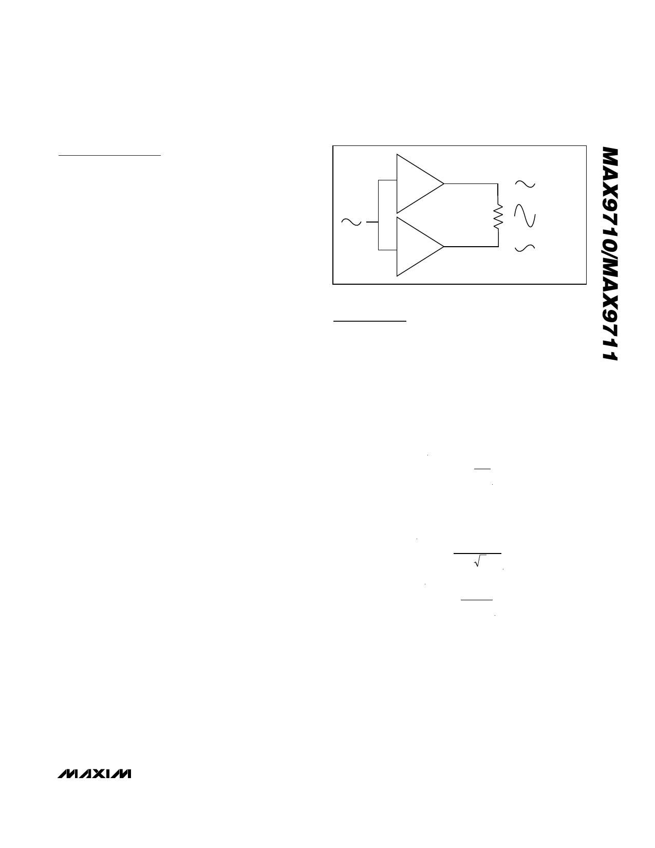
+1
VOUT(P-P)
2 x VOUT(P-P)
-1
VOUT(P-P)
Figure 1. Bridge-Tied Load Configuration
Applications Information
BTL Amplifier
The MAX9710/MAX9711 are designed to drive a load
differentially, a configuration referred to as BTL. The
BTL configuration (Figure 1) offers advantages over the
single-ended configuration, where one side of the load
is connected to ground. Driving the load differentially
doubles the output voltage compared to a single-
ended amplifier under similar conditions. Thus, the dif-
ferential gain of the device is twice the closed-loop gain
of the input amplifier. The effective gain is given by:
AVD
=
2
×
RF
RIN
Substituting 2 x VOUT(P-P) for VOUT(P-P) into the follow-
ing equations yields four times the output power due to
doubling of the output voltage:
VRMS
=
VOUT(P−P)
22
POUT
=
VRMS2
RL
Since the differential outputs are biased at midsupply,
there is no net DC voltage across the load. This elimi-
nates the need for DC-blocking capacitors required for
single-ended amplifiers. These capacitors can be
large, expensive, consume board space, and degrade
low-frequency performance.
_______________________________________________________________________________________ 7
Share Link: 