LCMXO1200E-3MN100I 查看數據表(PDF) - Lattice Semiconductor
零件编号
产品描述 (功能)
生产厂家
LCMXO1200E-3MN100I Datasheet PDF : 95 Pages
| |||
Lattice Semiconductor
Architecture
MachXO Family Data Sheet
Modes of Operation
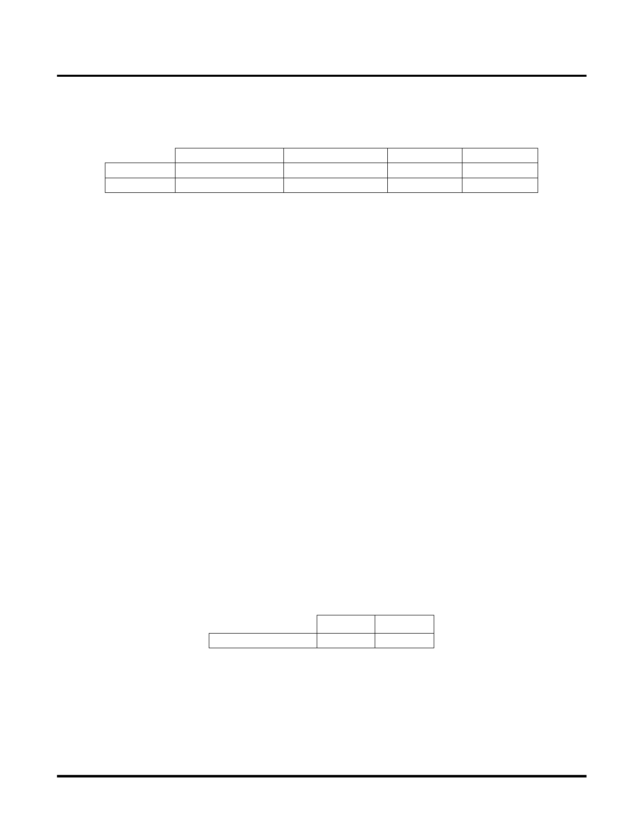
Each Slice is capable of four modes of operation: Logic, Ripple, RAM, and ROM. The Slice in the PFF is capable of
all modes except RAM. Table 2-2 lists the modes and the capability of the Slice blocks.
Table 2-2. Slice Modes
PFU Slice
PFF Slice
Logic
LUT 4x2 or LUT 5x1
LUT 4x2 or LUT 5x1
Ripple
2-bit Arithmetic Unit
2-bit Arithmetic Unit
RAM
SP 16x2
N/A
ROM
ROM 16x1 x 2
ROM 16x1 x 2
Logic Mode: In this mode, the LUTs in each Slice are configured as 4-input combinatorial lookup tables (LUT4). A
LUT4 can have 16 possible input combinations. Any logic function with four inputs can be generated by program-
ming this lookup table. Since there are two LUT4s per Slice, a LUT5 can be constructed within one Slice. Larger
lookup tables such as LUT6, LUT7, and LUT8 can be constructed by concatenating other Slices.
Ripple Mode: Ripple mode allows the efficient implementation of small arithmetic functions. In ripple mode, the fol-
lowing functions can be implemented by each Slice:
• Addition 2-bit
• Subtraction 2-bit
• Add/Subtract 2-bit using dynamic control
• Up counter 2-bit
• Down counter 2-bit
• Ripple mode multiplier building block
• Comparator functions of A and B inputs
- A greater-than-or-equal-to B
- A not-equal-to B
- A less-than-or-equal-to B
Two additional signals, Carry Generate and Carry Propagate, are generated per Slice in this mode, allowing fast
arithmetic functions to be constructed by concatenating Slices.
RAM Mode: In this mode, distributed RAM can be constructed using each LUT block as a 16x2-bit memory.
Through the combination of LUTs and Slices, a variety of different memories can be constructed.
The ispLEVER design tool supports the creation of a variety of different size memories. Where appropriate, the
software will construct these using distributed memory primitives that represent the capabilities of the PFU.
Table 2-3 shows the number of Slices required to implement different distributed RAM primitives. Figure 2-6 shows
the distributed memory primitive block diagrams. Dual port memories involve the pairing of two Slices. One Slice
functions as the read-write port, while the other companion Slice supports the read-only port. For more information
on RAM mode in MachXO devices, please see details of additional technical documentation at the end of this data
sheet.
Table 2-3. Number of Slices Required For Implementing Distributed RAM
SPR16x2 DPR16x2
Number of Slices
1
2
Note: SPR = Single Port RAM, DPR = Dual Port RAM
2-5
Share Link: 