MEA1D0515DC 查看數據表(PDF) - Murata Power Solutions
零件编号
产品描述 (功能)
生产厂家
MEA1D0515DC Datasheet PDF : 8 Pages
| |||
MEA1 Series
1kVDC Isolated 1W Dual Output DC/DC Converters
APPLICATION NOTES
Minimum load
The minimum load to meet datasheet specification is 10% of the full rated load across the specified input voltage range. Lower than 10% minimum loading will result in
an increase in output voltage, which may rise to typically double the specified output voltage if the output load falls to less than 5%.
Capacitive loading and start up
Typical start up times for this series, with a typical input voltage rise time of 2.2μs and output capacitance of 10μF, are shown in the table below. The product
series will start into a capacitance of 47μF with an increased start time, however, the maximum recommended output capacitance is 10μF.
MEA1D0505xC
MEA1D0509xC
MEA1D0512xC
MEA1D0515xC
MEA1D1205xC
MEA1D1209xC
MEA1D1212xC
MEA1D1215xC
MEA1D1505xC
MEA1D1509xC
Start-up time
μs
939
2872
5325
8895
1150
3716
6912
10810
883
3160
MEA1D1512xC
MEA1D1515xC
MEA1D2405xC
MEA1D2409xC
MEA1D2412xC
MEA1D2415xC
MEA1D4805xC
MEA1D4809xC
MEA1D4812xC
MEA1D4815xC
Start-up time
μs
5630
8585
472
1473
2643
4348
586
1705
2995
4722
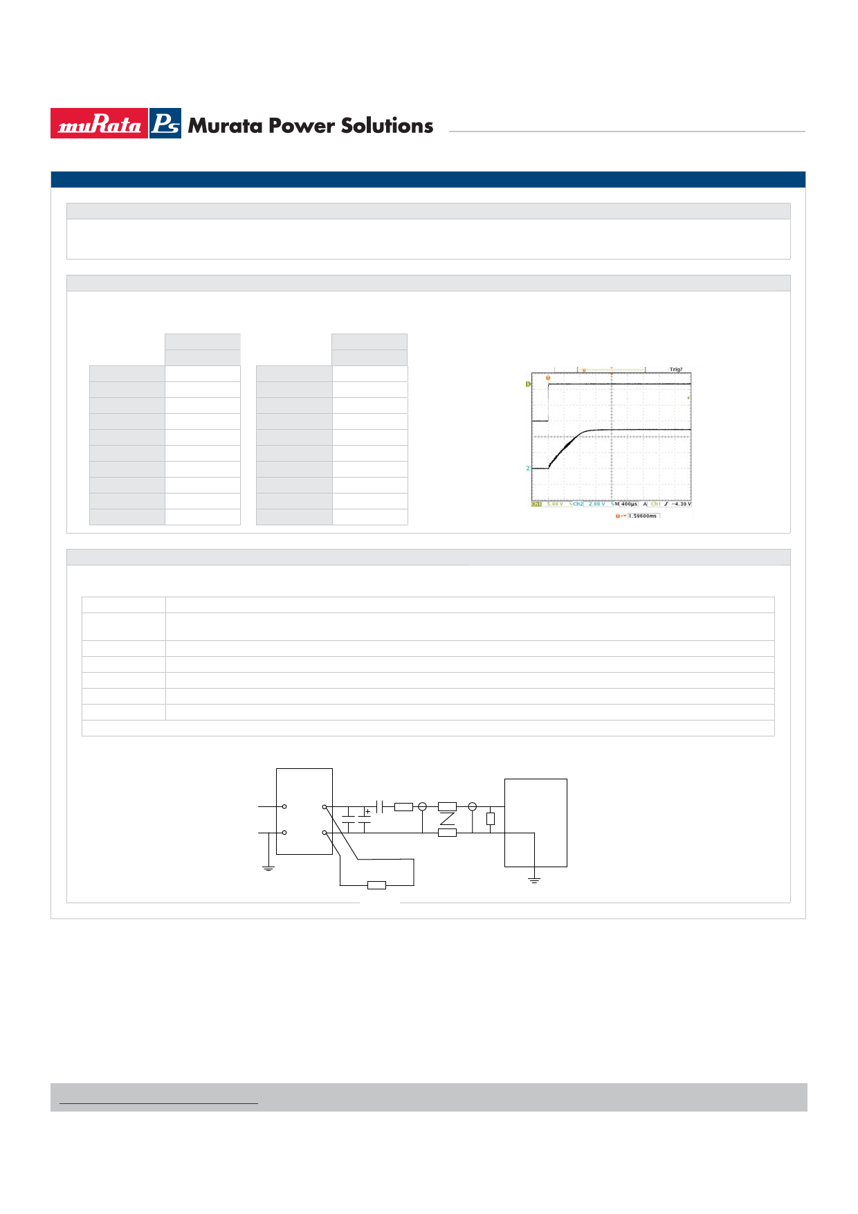
Typical Start-Up Wave Form
Ripple & Noise Characterisation Method
Ripple and noise measurements are performed with the following test configuration.
C1
1μF X7R multilayer ceramic capacitor, voltage rating to be a minimum of 3 times the output voltage of the DC/DC converter
C2
10μF tantalum capacitor, voltage rating to be a minimum of 1.5 times the output voltage of the DC/DC converter with an ESR of less
than 100mΩ at 100 kHz
C3
100nF multilayer ceramic capacitor, general purpose
R1
450Ω resistor, carbon film, ±1% tolerance
R2
50Ω BNC termination
T1
3T of the coax cable through a ferrite toroid
RLOAD
Resistive load to the maximum power rating of the DC/DC converter. Connections should be made via twisted wires
Measured values are multiplied by 10 to obtain the specified values.
Differential Mode Noise Test Schematic
SUPPLY
DC/DC Converter
++
Input Output
--
C1 C2 C3 R1
OSCILLOSCOPE
T1
R2
Y INPUT
R LOAD
www.murata-ps.com/support
KDC_MEA1.C06 Page 4 of 8
Share Link: 