MAX6322HPUK35DY-T жҹҘзңӢж•ёж“ҡиЎЁпјҲPDFпјү - Maxim Integrated
йӣ¶д»¶зј–еҸ·
дә§е“ҒжҸҸиҝ° (еҠҹиғҪ)
з”ҹдә§еҺӮ家
MAX6322HPUK35DY-T Datasheet PDF : 16 Pages
| |||
5-Pin ВөP Supervisory Circuits with
Watchdog and Manual Reset
Bidirectional RESET Output
The MAX6316M/MAX6318MH/MAX6319MH are designed
to interface with ВөPs that have bidirectional reset pins,
such as the Motorola 68HC11. Like an open-drain output,
these devices allow the ВөP or other devices to pull the
bidirectional reset (RESET) low and assert a reset condi-
tion. However, unlike a standard open-drain output, it
includes the commonly specified 4.7kв„Ұ pull-up resistor
with a P-channel active pull-up in parallel.
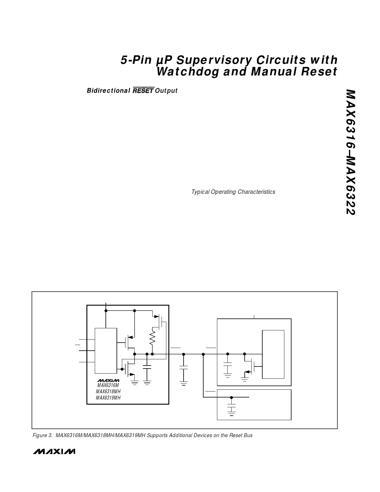
This configuration allows the MAX6316M/MAX6318MH/
MAX6319MH to solve a problem associated with ВөPs
that have bidirectional reset pins in systems where sev-
eral devices connect to RESET (Figure 3). These ВөPs
can often determine if a reset was asserted by an exter-
nal device (i.e., the supervisor IC) or by the ВөP itself
(due to a watchdog fault, clock error, or other source),
and then jump to a vector appropriate for the source of
the reset. However, if the ВөP does assert reset, it does
not retain the information, but must determine the
cause after the reset has occurred.
The following procedure describes how this is done in
the Motorola 68HC11. In all cases of reset, the ВөP pulls
RESET low for about four external-clock cycles. It then
releases RESET, waits for two external-clock cycles,
then checks RESETвҖҷs state. If RESET is still low, the ВөP
concludes that the source of the reset was external
and, when RESET eventually reaches the high state, it
jumps to the normal reset vector. In this case, stored-
state information is erased and processing begins from
scratch. If, on the other hand, RESET is high after a
delay of two external-clock cycles, the processor
knows that it caused the reset itself and can jump to a
different vector and use stored-state information to
determine what caused the reset.
A problem occurs with faster ВөPs; two external-clock
cycles are only 500ns at 4MHz. When there are several
devices on the reset line, and only a passive pull-up resis-
tor is used, the input capacitance and stray capacitance
can prevent RESET from reaching the logic high state (0.8
x VCC) in the time allowed. If this happens, all resets will
be interpreted as external. The ВөP output stage is guaran-
teed to sink 1.6mA, so the rise time can not be reduced
considerably by decreasing the 4.7kв„Ұ internal pull-up
resistance. See Bidirectional Pull-Up Characteristics in the
Typical Operating Characteristics.
The MAX6316M/MAX6318MH/MAX6319MH overcome
this problem with an active pull-up FET in parallel with the
4.7kв„Ұ resistor (Figures 4 and 5). The pull-up transistor
holds RESET high until the ВөP reset I/O or the supervisory
circuit itself forces the line low. Once RESET goes below
VPTH, a comparator sets the transition edge flip-flop, indi-
cating that the next transition for RESET will be low to
high. When RESET is released, the 4.7kв„Ұ resistor pulls
RESET up toward VCC. Once RESET rises above VPTH
but is below (0.85 x VCC), the active P-channel pull-up
turns on. Once RESET rises above (0.85 x VCC) or the
2Вөs one-shot times out, the active pull-up turns off. The
parallel combination of the 4.7kв„Ұ pull-up and the
VCC
VCC
WDI*
MR**
RESET***
RESET
CIRCUITRY
4.7k
RESET
RESET
CIN
CSTRAY
68HC11
CIN
RESET
CIRCUITRY
MAX6316M
MAX6318MH
MAX6319MH
* MAX6316M/MAX6318MH
** MAX6316M/MAX6319MH
*** ACTIVE-HIGH PUSH/PULL MAX6318MH/MAX6319MH
RESET
CIN
OTHER DEVICES
Figure 3. MAX6316M/MAX6318MH/MAX6319MH Supports Additional Devices on the Reset Bus
_______________________________________________________________________________________ 7
Share Link: 