180RKI80PBF 查看數據表(PDF) - Vishay Semiconductors
零件编号
产品描述 (功能)
生产厂家
180RKI80PBF Datasheet PDF : 8 Pages
| |||
180RKI...PbF, 181RKI...PbF Series
Phase Control Thyristors Vishay High Power Products
(Stud Version), 180 A
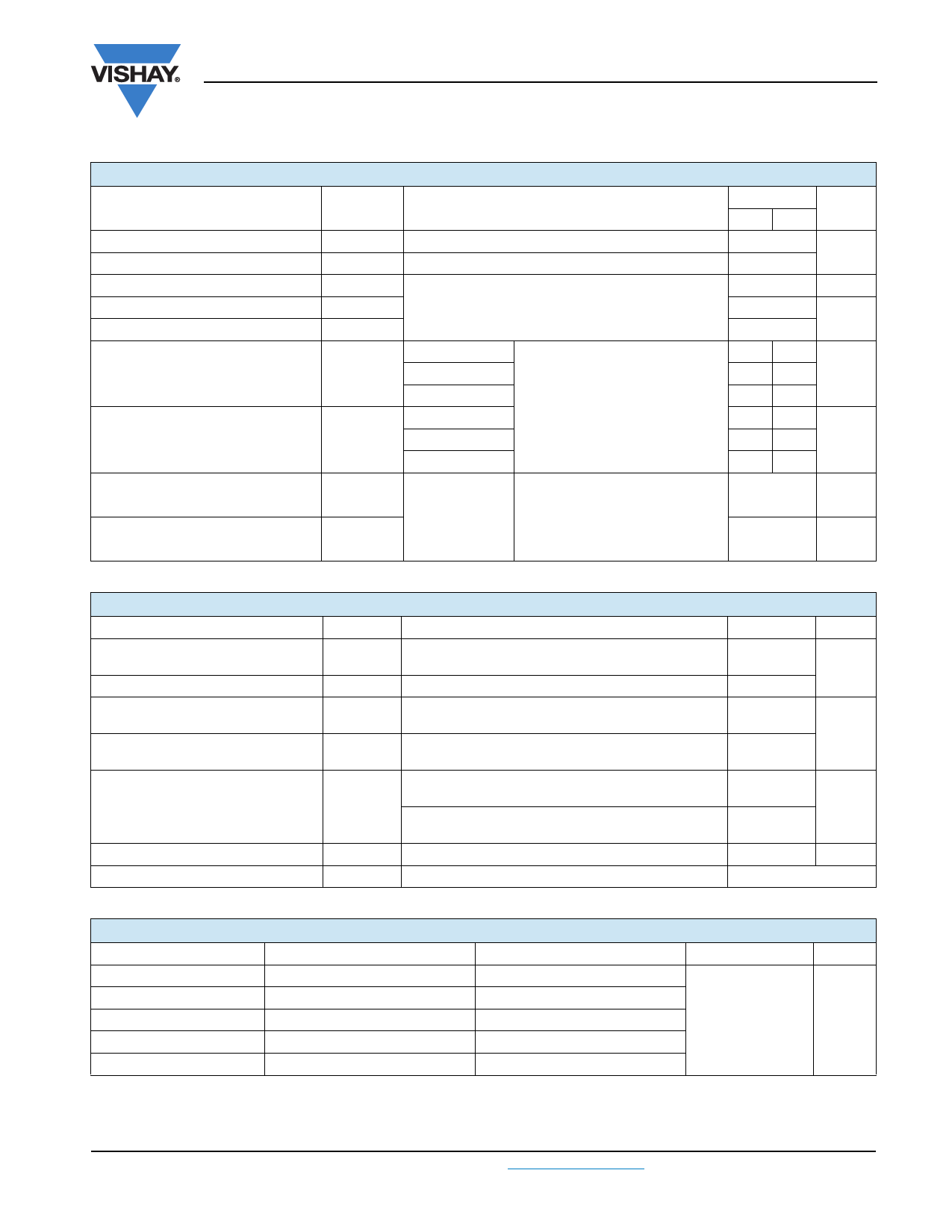
TRIGGERING
PARAMETER
Maximum peak gate power
Maximum average gate power
Maximum peak positive gate current
Maximum peak positive gate voltage
Maximum peak negative gate voltage
DC gate current required to trigger
DC gate voltage required to trigger
DC gate current not to trigger
DC gate voltage not to trigger
SYMBOL
PGM
PG(AV)
IGM
+ VGM
- VGM
IGT
VGT
IGD
VGD
TEST CONDITIONS
TJ = TJ maximum, tp ≤ 5 ms
TJ = TJ maximum, f = 50 Hz, d% = 50
TJ = TJ maximum, tp ≤ 5 ms
TJ = - 40 °C
TJ = 25 °C
TJ = 125 °C
TJ = - 40 °C
TJ = 25 °C
TJ = 125 °C
TJ = TJ maximum
Maximum required gate trigger/
current/voltage are the lowest
value which will trigger all units
12 V anode to cathode applied
Maximum gate current/voltage not
to trigger is the maximum value
which will not trigger any unit with
rated VDRM anode to cathode
applied
VALUES
TYP. MAX.
10
2.0
3.0
20
5.0
130 -
65 150
35
-
2.0
-
1.2 2.5
0.9
-
UNITS
W
A
V
mA
V
10
mA
0.25
V
THERMAL AND MECHANICAL SPECIFICATIONS
PARAMETER
SYMBOL
TEST CONDITIONS
Maximum operating junction
temperature range
TJ
Maximum storage temperature range
Maximum thermal resistance,
junction to case
TStg
RthJC
DC operation
Maximum thermal resistance,
junction to ambient
RthCS
Mounting surface, smooth, flat and greased
Mounting force, ± 10 %
Non-lubricated threads
Lubricated threads
Approximate weight
Case style
See dimensions - link at the end of datasheet
VALUES UNITS
- 40 to 125
°C
- 40 to 150
0.15
K/W
0.04
31
(275)
24.5
(210)
N·m
(lbf · in)
280
g
TO-209AB (TO-93)
ΔRthJC CONDUCTION
CONDUCTION ANGLE
SINUSOIDAL CONDUCTION
RECTANGULAR CONDUCTION TEST CONDITIONS UNITS
180°
0.050
0.032
120°
0.063
0.059
90°
0.080
60°
0.118
0.082
0.124
TJ = TJ maximum
K/W
30°
0.225
0.228
Note
• The table above shows the increment of thermal resistance RthJC when devices operate at different conduction angles than DC
Document Number: 94382
Revision: 03-Nov-09
For technical questions, contact: indmodules@vishay.com
www.vishay.com
3
Share Link: 