DS1340 查看數據表(PDF) - Dallas Semiconductor -> Maxim Integrated
零件编号
产品描述 (功能)
生产厂家
DS1340 Datasheet PDF : 13 Pages
| |||
I2C RTC with Trickle Charger
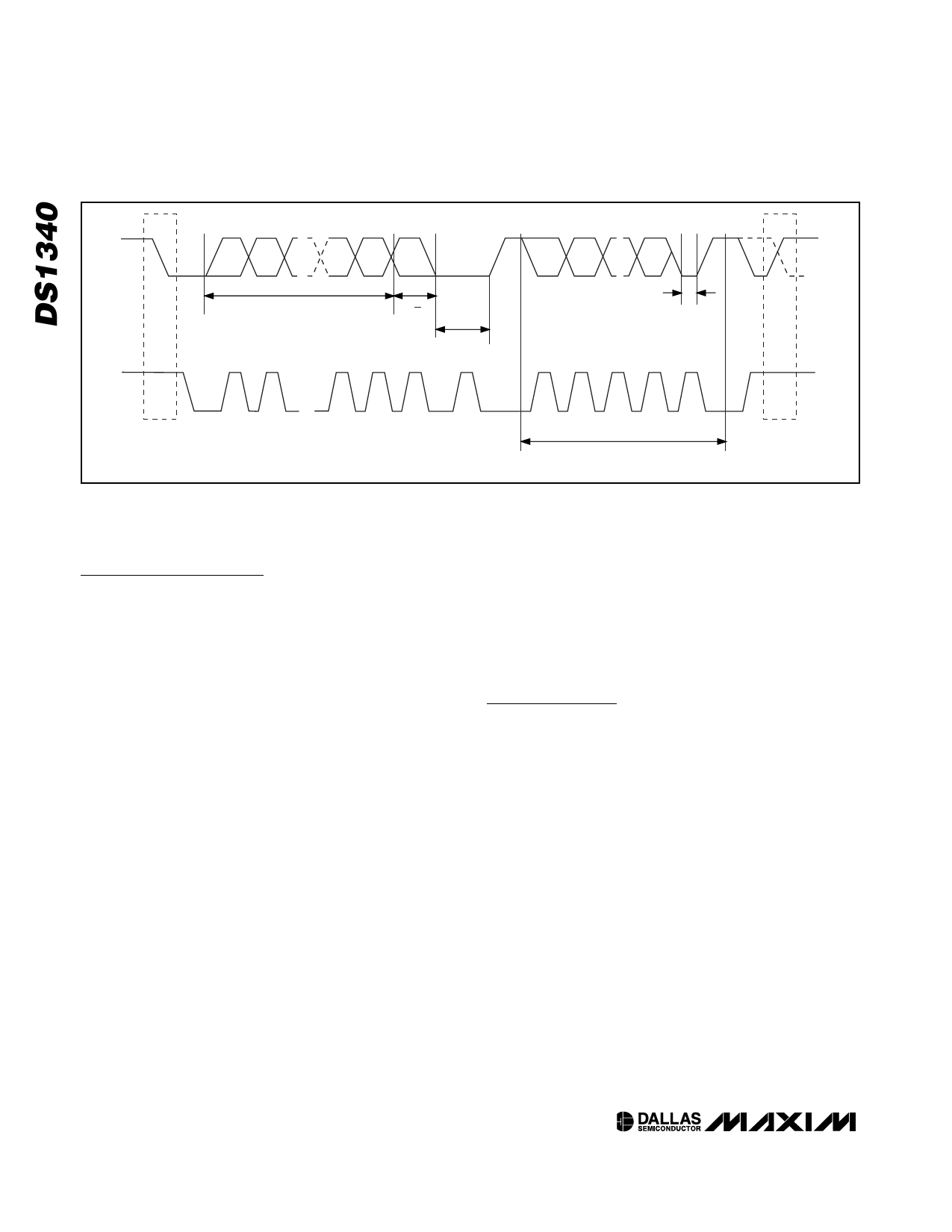
SDA
MSB
SLAVE ADDRESS
R/W
DIRECTION
BIT
ACKNOWLEDGEMENT
SIGNAL FROM RECEIVER
ACKNOWLEDGEMENT
SIGNAL FROM RECEIVER
SCL
START
CONDITION
1
2
6
7
8
9
ACK
Figure 7. I2C Data Transfer Overview
1
2
3–7
8
9
ACK
REPEATED IF MORE BYTES
ARE TRANSFERED
STOP
CONDITION
OR REPEATED
START
CONDITION
Bits 6 to 0: All other bits in the flag register read as 0
and cannot be written.
Clock Calibration
The DS1340 provides a digital clock calibration feature
to allow compensation for crystal and temperature vari-
ations. The calibration circuit adds or subtracts counts
from the oscillator divider chain at the divide-by-256
stage. The number of pulses blanked (subtracted for
negative calibration) or inserted (added for positive cal-
ibration) depends upon the value loaded into the five
calibration bits (CAL4–CAL0) located in the control reg-
ister. Adding counts speeds the clock up and subtract-
ing counts slows the clock down.
The calibration bits can be set to any value between 0
and 31 in binary form. Bit 5 of the control register, S, is
the sign bit. A value of 1 for the S bit indicates positive
calibration, while a value of 0 represents negative cali-
bration. Calibration occurs within a 64-minute cycle.
The first 62 minutes in the cycle can, once per minute,
have a one-second interval where the calibration is per-
formed. Negative calibration blanks 128 cycles of the
32,768Hz oscillator, slowing the clock down. Positive
calibration inserts 256 cycles of the 32,768Hz oscillator,
speeding the clock up. If a binary 1 is loaded into the
calibration bits, only the first two minutes in the 64-
minute cycle are modified. If a binary 6 is loaded, the
first 12 minutes are affected, and so on. Therefore,
each calibration step either adds 512 or subtracts 256
oscillator cycles for every 125,829,120 actual 32,678Hz
oscillator cycles (64 minutes). This equates to
+4.068ppm or -2.034ppm of adjustment per calibration
step. If the oscillator runs at exactly 32,768Hz, each of
the 31 increments of the calibration bits would repre-
sent +10.7 or -5.35 seconds per month, corresponding
to +5.5 or -2.75 minutes per month.
For example, if using the FT function, a reading of
512.01024Hz would indicate a +20ppm oscillator fre-
quency error, requiring a -10(00 1010) value to be
loaded in the S bit and the five calibration bits.
Note: Setting the calibration bits does not affect the fre-
quency test output frequency. Also note that writing to
the control register resets the divider chain.
I2C Serial Data Bus
The DS1340 supports a bidirectional I2C bus and data
transmission protocol. A device that sends data onto
the bus is defined as a transmitter and a device receiv-
ing data as a receiver. The device that controls the
message is called a master. The devices that are con-
trolled by the master are slaves. A master device that
generates the serial clock (SCL), controls the bus
access, and generates the START and STOP condi-
tions must control the bus. The DS1340 operates as a
slave on the I2C bus. Connections to the bus are made
through the open-drain I/O lines SDA and SCL. Within
the bus specifications a standard mode (100kHz max
clock rate) and a fast mode (400kHz max clock rate)
are defined. The DS1340 works in both modes.
The following bus protocol has been defined (Figure 7):
• Data transfer can be initiated only when the bus is
not busy.
• During data transfer, the data line must remain
stable whenever the clock line is high. Changes in
the data line while the clock line is high are inter-
preted as control signals.
10 ____________________________________________________________________
Share Link: 