A5368 查看數據表(PDF) - Allegro MicroSystems
零件编号
产品描述 (功能)
生产厂家
A5368 Datasheet PDF : 8 Pages
| |||
5368
SMOKE DETECTOR
WITH INTERCONNECT
AND TIMER
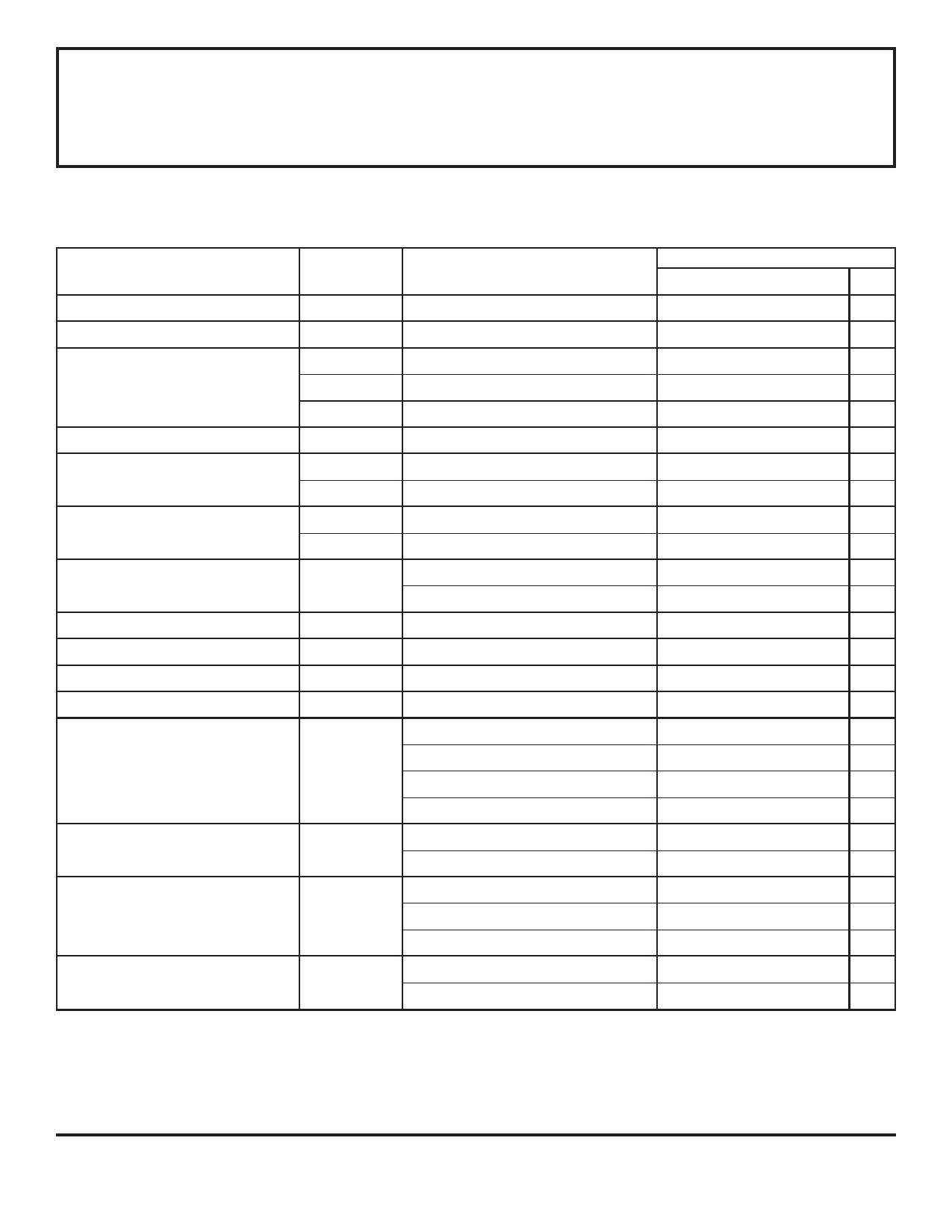
ELECTRICAL CHARACTERISTICS at TA = +25°C, VDD = 9.0 V, VSS = 0 V, C12 = 0.1 µF,
R7 = 8.2 MΩ (unless otherwise noted).
Characteristic
Test
Pin
Test Conditions
Min.
Limits
Typ. Max.
Units
Supply Voltage Range
6
Operating
6.0
9.0
12
V
Detector Input Current
Input Offset Voltage
15
14-15
0 to 40% RH, VIN = 0 to 9.0 V
Active Guard
—
—
±1.0
pA
—
—
±100 mV
16-15
Active Guard
—
—
±100 mV
15-13
Detect Comparator
—
—
±50
mV
Hysteresis
13
No Alarm to Alarm
90
130
170
mV
Common Mode Range
Active Guard Impedance
Oscillator Period
14-15
13-15
14
16
12
Guard Amplifier
Smoke Comparator
to VSS
to VSS
No Alarm
2.0
0.5
—
—
1.34
— VDD - 0.5 V
— VDD - 2.0 V
10
—
kΩ
500
—
kΩ
1.67
2.00
s
Alarm
32
40
48
ms
Oscillator Pulse Width
4
8.0
10
12
ms
Timer Period
4
After Pin 1 High-to-Low, No Smoke 8.0
10
12
min
Low Voltage Threshold
Sensitivity Adj. Voltage
Horn Output Voltage
Horn Output ON Time
6
13
10-11
10-11
TA = 0 to 50°C
V13/VDD, pin 13 open circuit
IOUT = 16 mA, VDD = 9.0 V
IOUT = 16 mA, VDD = 7.2 V
IOUT = -16 mA, VDD = 9.0 V
IOUT = -16 mA, VDD = 7.2 V
Alarm (see figure, time “A”)
7.2
—
7.8
V
48.5
50
51.5
%
—
0.1
0.5
V
—
—
0.9
V
8.5
8.8
—
V
6.3
—
—
V
450
500
550
ms
Low Battery
8.0
10
12
ms
Horn Output OFF Time
10-11
Alarm (see figure, time “B”)
450
500
550
ms
Alarm (see figure, time “C”)
1350 1500 1650 ms
Low Battery
32
40
48
s
Timer Start Logic Levels
1
VIH
VIL
4.5
—
—
V
—
—
2.5
V
NOTE 1: Negative current is defined as coming out of (sourcing) the specified device pin.
Continued next page . . .
NOTE 2: Alarm (Smoke) Condition is defined as V15 < V13; No Alarm (No Smoke) Condition as V15 > V13.
Share Link: 