AM29LV001BB-45RECB 查看數據表(PDF) - Advanced Micro Devices
零件编号
产品描述 (功能)
生产厂家
AM29LV001BB-45RECB
Advanced Micro Devices

AM29LV001BB-45RECB Datasheet PDF : 40 Pages
| |||
Autoselect Mode
The autoselect mode provides manufacturer and
device identification, and sector protection verification,
through identifier codes output on DQ7–DQ0. This
mode is primarily intended for programming equipment
to automatically match a device to be programmed with
its corresponding programming algorithm. However,
the autoselect codes can also be accessed in-system
through the command register.
When using programming equipment, the autoselect
mode requires VID (11.5 V to 12.5 V) on address pin
A9. Address pins A6, A1, and A0 must be as shown in
Table 4. In addition, when verifying sector protection,
the sector address must appear on the appropriate
highest order address bits (see Table 2). Table 4 shows
the remaining address bits that are don’t care. When all
necessary bits have been set as required, the program-
ming equipment may then read the corresponding
identifier code on DQ7-DQ0.
To access the autoselect codes in-system, the host
system can issue the autoselect command via the
command register, as shown in Table 5. This method
does not require VID. See “Command Definitions” for
details on using the autoselect mode.
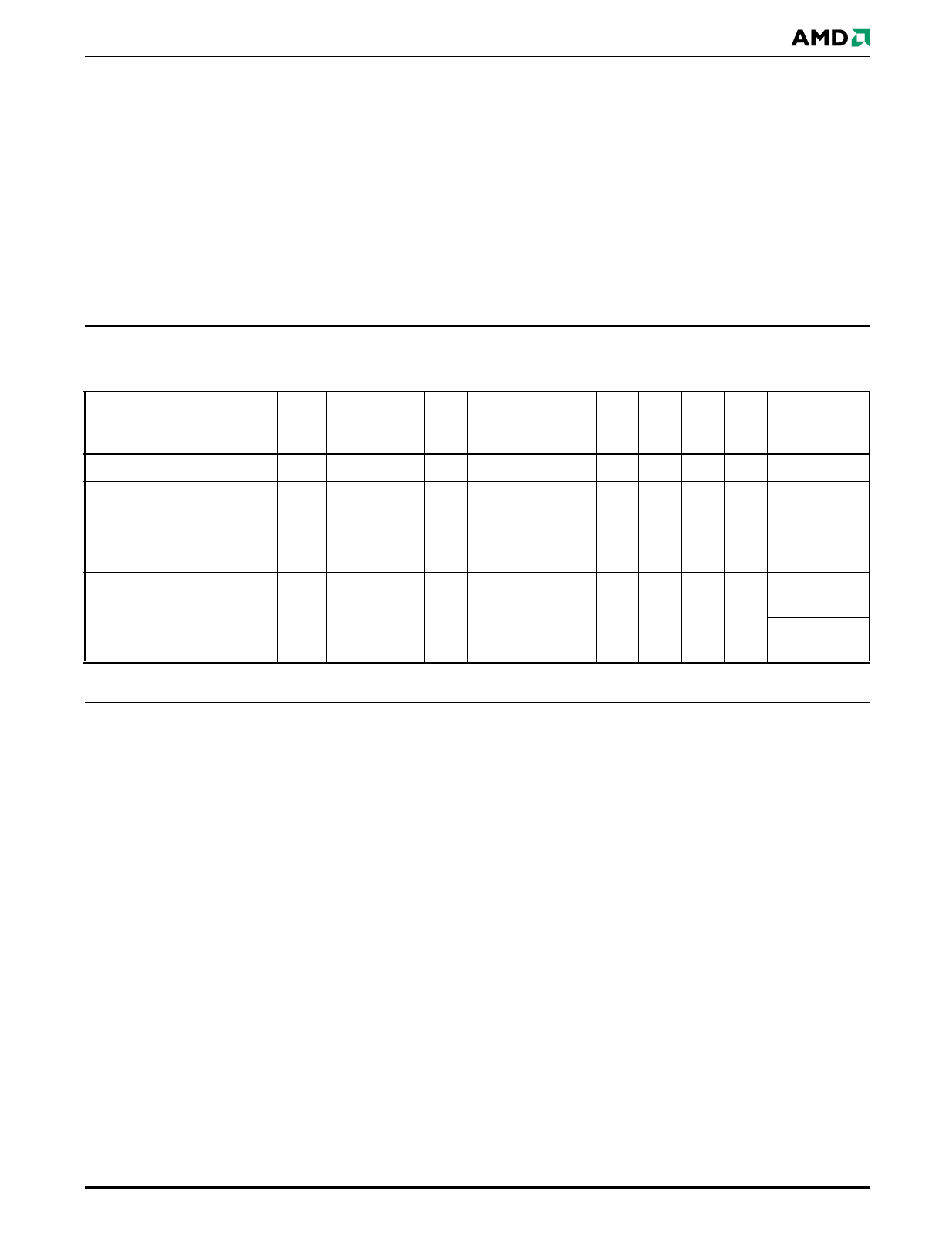
Table 4. Am29LV001B Autoselect Codes
Description
Manufacturer ID: AMD
Device ID: Am29LV001BT
(Top Boot Block)
Device ID: Am29LV001BB
(Bottom Boot Block)
A16 A11
A8
A5
to to
to
to
CE# OE# WE# A12 A10 A9 A7 A6 A2 A1 A0
L
L
H
X
X VID X
L
X
L
L
L
L
H
X
X VID X
L
X
LH
L
L
H
X
X VID X
L
X
LH
DQ7
to
DQ0
01h
EDh
6Dh
01h
(protected)
Sector Protection Verification L
L
H SA X VID X
L
X
H
L
00h
(unprotected)
L = Logic Low = VIL, H = Logic High = VIH, SA = Sector Address, X = Don’t care.
Sector Protection/Unprotection
The hardware sector protection feature disables both
program and erase operations in any sector. The hard-
ware sector unprotection feature re-enables both
program and erase operations in previously protected
sectors. Sector protection/unprotection can be imple-
mented via two methods.
The primary method requires VID on the RESET# pin
only, and can be implemented either in-system or via
programming equipment. Figure 1 shows the algo-
rithms and Figure 21 shows the timing diagram. This
method uses standard microprocessor bus cycle
timing. For sector unprotect, all unprotected sectors
must first be protected prior to the first sector unprotect
write cycle.
The alternate method intended only for programming
equipment requires VID on address pin A9, OE#, and
RESET#. This method is compatible with programmer
routines written for earlier 3.0 volt-only AMD flash
devices. Publication number 22134 contains further
details; contact an AMD representative to request a
copy.
The device is shipped with all sectors unprotected.
AMD offers the option of programming and protecting
sectors at its factory prior to shipping the device
through AMD’s ExpressFlash™ Service. Contact an
AMD representative for details.
It is possible to determine whether a sector is protected
or unprotected. See “Autoselect Mode” for details.
Temporary Sector Unprotect
This feature allows temporary unprotection of previ-
ously protected sectors to change data in-system. The
Sector Unprotect mode is activated by setting the
RESET# pin to VID. During this mode, formerly pro-
tected sectors can be programmed or erased by
selecting the sector addresses. Once VID is removed
from the RESET# pin, all the previously protected
sectors are protected again. Figure 2 shows the algo-
rithm, and Figure 20 shows the timing diagrams, for
this feature.
September 26, 2002
Am29LV001B
11
Share Link: