AM29F010B-70FC 查看數據表(PDF) - Advanced Micro Devices
零件编号
产品描述 (功能)
生产厂家
AM29F010B-70FC
Advanced Micro Devices

AM29F010B-70FC Datasheet PDF : 33 Pages
| |||
PRELIMINARY
Program and Erase Operation Status
During an erase or program operation, the system may
check the status of the operation by reading the status
bits on DQ7–DQ0. Standard read cycle timings and ICC
read specifications apply. Refer to “Write Operation
Status” for more information, and to each AC Charac-
teristics section in the appropriate data sheet for timing
diagrams.
Standby Mode
When the system is not reading or writing to the device,
it can place the device in the standby mode. In this
mode, current consumption is greatly reduced, and the
outputs are placed in the high impedance state, inde-
pendent of the OE# input.
The device enters the CMOS standby mode when the
CE# pin is held at VCC ± 0.5 V. (Note that this is a more
restricted voltage range than VIH.) The device enters
the TTL standby mode when CE# is held at VIH. The
device requires the standard access time (tCE) before
it is ready to read data.
If the device is deselected during erasure or program-
ming, the device draws active current until the
operation is completed.
ICC3 in the DC Characteristics tables represents the
standby current specification.
Output Disable Mode
When the OE# input is at VIH, output from the device is
disabled. The output pins are placed in the high imped-
ance state.
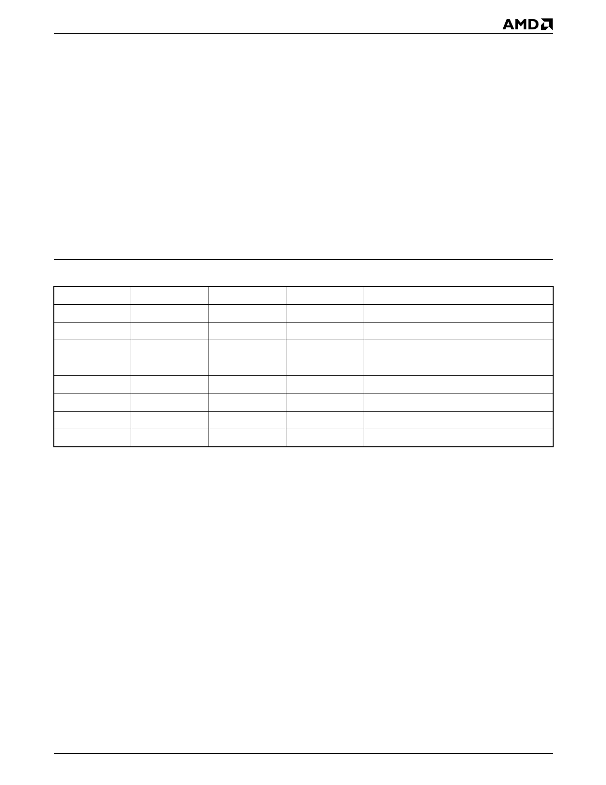
Sector
SA0
SA1
SA2
SA3
SA4
SA5
SA6
SA7
Table 2. Am29F010B Sector Addresses Table
A16
A15
A14
Address Range
0
0
0
00000h-03FFFh
0
0
1
04000h-07FFFh
0
1
0
08000h-0BFFFh
0
1
1
0C000h-0FFFFh
1
0
0
10000h-13FFFh
1
0
1
14000h-17FFFh
1
1
0
18000h-1BFFFh
1
1
1
1C000h-1FFFFh
Autoselect Mode
The autoselect mode provides manufacturer and de-
vice identification, and sector protection verification,
through identifier codes output on DQ7–DQ0. This
mode is primarily intended for programming equipment
to automatically match a device to be programmed with
its corresponding programming algorithm. However,
the autoselect codes can also be accessed in-system
through the command register.
When using programming equipment, the autoselect
mode requires VID on address pin A9. Address pins A6,
A1, and A0 must be as shown in Autoselect Codes
(High Voltage Method) table. In addition, when verify-
ing sector protection, the sector address must appear
on the appropriate highest order address bits. Refer to
the corresponding Sector Address Tables. The Com-
mand Definitions table shows the remaining address
bits that are don’t care. When all necessary bits have
been set as required, the programming equipment may
then read the corresponding identifier code on DQ7–
DQ0.
To access the autoselect codes in-system, the host
system can issue the autoselect command via the
command register, as shown in the Command Defini-
tions table. This method does not require VID. See
“Command Definitions” for details on using the autose-
lect mode.
Am29F010B
9
Share Link: