A1103 查看數據表(PDF) - Allegro MicroSystems
零件编号
产品描述 (功能)
生产厂家
A1103 Datasheet PDF : 12 Pages
| |||
A1101, A1102, A1103,
A1104, and A1106
Continuous-Time Switch Family
ELECTRICAL OPERATING CHARACTERISTICS over full operating voltage and ambient temperature ranges, unless otherwise noted
Characteristic
Symbol
Test Conditions
Min. Typ. Max. Units
Supply Voltage1
Output Leakage Current
Output On Voltage
Power-On Time2
Output Rise Time3
Output Fall Time3
Supply Current
Reverse Battery Current
VCC
IOUTOFF
VOUT(SAT)
tPO
tr
tf
ICCON
ICCOFF
IRCC
Operating, TJ < 165°C
VOUT = 24 V, B < BRP
IOUT = 20 mA, B > BOP
Slew rate (dVCC/dt) < 2.5 V/μs, B > BOP + 5 G or
B < BRP – 5 G
VCC = 12 V, RLOAD = 820 Ω, CS = 12 pF
VCC = 12 V, RLOAD = 820 Ω, CS = 12 pF
B > BOP
B < BRP
VRCC = –30 V
3.8
–
24
V
–
–
10
μA
–
215 400 mV
–
–
4
μs
–
–
400 ns
–
–
400 ns
–
4.1 7.5 mA
–
3.8 7.5 mA
–
–
–10 mA
Supply Zener Clamp Voltage
VZ
ICC = 10.5 mA; TA = 25°C
32
–
–
V
Supply Zener Current4
IZ
VZ = 32 V; TA = 25°C
–
1 Maximum voltage must be adjusted for power dissipation and junction temperature, see Power Derating section.
2 For VCC slew rates greater than 250 V/μs, and TA = 150°C, the Power-On Time can reach its maximum value.
3 CS =oscilloscope probe capacitance.
4 Maximum current limit is equal to the maximum ICC(max) + 3 mA.
– 10.5 mA
DEVICE QUALIFICATION PROGRAM
Contact Allegro for information.
EMC (Electromagnetic Compatibility) REQUIREMENTS
Contact Allegro for information.
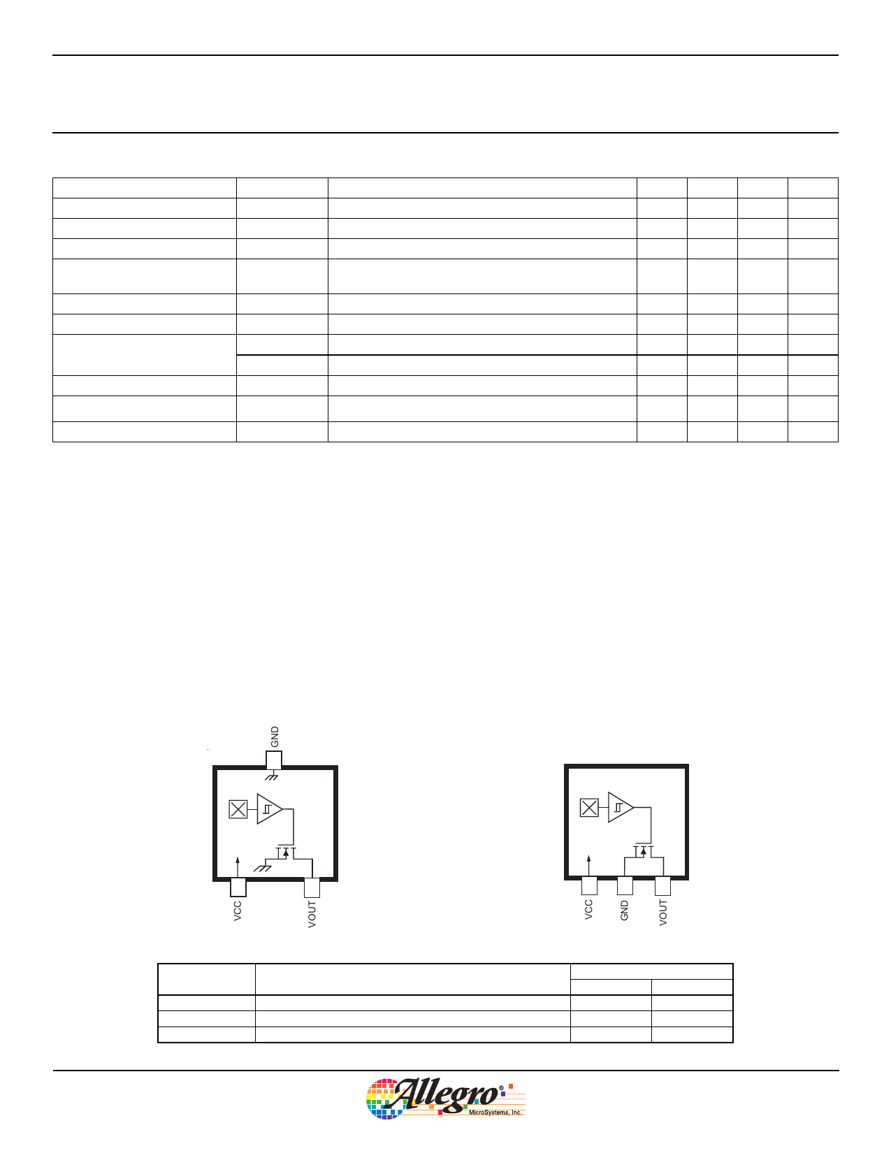
Package LH
3
Package UA, 3-pin SIP
1
2
Terminal List
Name
VCC
VOUT
GND
Description
Connects power supply to chip
Output from circuit
Ground
1
2
3
Number
Package LH Package UA
1
1
2
3
3
2
Allegro MicroSystems, Inc.
3
115 Northeast Cutoff
Worcester, Massachusetts 01615-0036 U.S.A.
1.508.853.5000; www.allegromicro.com
Share Link: 