AAT1157 查看數據表(PDF) - Analog Technology Inc
零件编号
产品描述 (功能)
生产厂家
AAT1157 Datasheet PDF : 14 Pages
| |||
AAT1157
1MHz 1.2A Buck DC/DC Converter
P = IO2 ⋅ (RDSON(HS) ⋅ VO + RDSON(LS) ⋅ (VIN - VO))
VIN
+ (tsw ⋅ F ⋅ IO ⋅ VIN + IQ) ⋅ VIN
Where IQ is the AAT1157 quiescent current.
Once the total losses have been determined, the
junction temperature can be derived from the θJA for
the QFN package. Close attention should be paid to
the proper layout for the QFN package. Proper size
and placement of thermal routing vias below the
central paddle is necessary for good heat transfer to
other PCB layers and their ground planes. The θJA
for the QFN package with no connection to the cen-
tral paddle is 50°C/W. The actual θJA will vary with
the number and type of vias. The PCB board size,
number of board layers, and ground plane charac-
teristics also influence the θJA. A good thermal con-
nection from the paddle to the PCB ground plane
layers can significantly reduce θJA.
TJ = P · ΘJA + TAMB
Adjustable Output
Resistors R3 and R4, as shown in Figure 1, force
the output to regulate higher than the 0.6V refer-
ence voltage level. The optimum value for R4 is
59kΩ. Values higher than this can cause stability
problems, while lower values can degrade light
load efficiency. For a 2.5V output with R4 set to
59kΩ, R3 is 187kΩ.
R3
=
⎛ VO
⎝VREF
-1⎞⎠
·
R4
=
⎛ 2.5V
⎝ 0.6V
-
1 ⎞⎠
·
59kΩ
=
187kΩ
Table 1: Suggested Component Values.
Output
Voltage
(V)
0.8
1.0
1.2
1.5
1.8
2.5
3.3
L1
(µH)
1.5 - 2.6
1.5 - 3.3
2.2 - 3.3
2.2 - 4.7
3.0 - 4.7
3.0 - 4.7
2.2 - 4.7
Output
R3 for
Capacitor R4 = 59kΩ
(C3-C4) (µF) (kΩ)
3x 22
19.6
2x 22
39.2
2x 22
59
2x 22
88.7
2x 22
118
2x 22
187
22
267
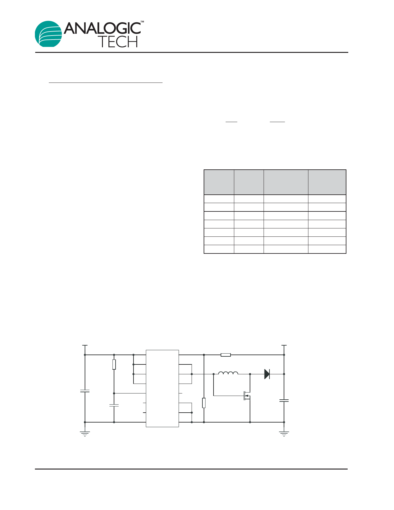
Buck-Boost Output
Figure 4 shows how to configure the AAT1157 in a
buck boost configuration with an external MOSFET
and Schottky diode. The converter has a 3.3V
600mA output with an input voltage ranging from
2.7V to 5.5V.
VIN 2.7V to 5.5V
C1
22µF
R1
100
C2
0.1µF
U1
AAT1157
12 VP
OUT 4
11 VP
LX 15
10 VP
LX 14
7 EN
LX 13
9 VCC
N/C 16
6 N/C
PGND 3
8 N/C
PGND 2
5 SGND PGND 1
R2
267k
L1
3.0µH
R3
59.0k
VO 3.3V/600mA
D1
MBRM120L
Q1
Si2302ADS
C3,C4
2x 22µF
L1 Sumida CDRH5D28-3R0
C1 Murata 22µF 10V X7R 1210 GRM32ER71A226KE20L
C3,C4 MuRata 22µF 6.3V X5R 0805 GRM21BR60J226ME39L
Figure 4: AAT1157 Buck Boost Converter.
10
1157.2005.11.1.4
Share Link: 