ACPL-K44T 查看數據表(PDF) - Avago Technologies
零件编号
产品描述 (功能)
生产厂家
ACPL-K44T Datasheet PDF : 11 Pages
| |||
Thermal Resistance Model for ACPL-K43T
The diagram of ACPL-K43T for measurement is shown in Figure 15. Here, one die is heated first and the temperatures of
all the dice are recorded after thermal equilibrium is reached. Then, the 2nd die is heated and all the dice temperatures
are recorded. With the known ambient temperature, the die junction temperature and power dissipation, the thermal
resistance can be calculated. The thermal resistance calculation can be cast in matrix form. This yields a 2 by 2 matrix for
our case of two heat sources.
R11 R12
R21 R22
X
P1
P2
=
T1
T2
1
8
R11 : Thermal Resistance of Die1 due to heating of Die1 (˚C/W)
R12 : Thermal Resistance of Die1 due to heating of Die2 (˚C/W)
R21 : Thermal Resistance of Die2 due to heating of Die1 (˚C/W)
R22 : Thermal Resistance of Die2 due to heating of Die2 (˚C/W)
P1 : Power dissipation of Die1 (W)
P2 : Power dissipation of Die2 (W)
2 Die1:
LED
3
4
Die2:
7
Detector
6
5
Figure 15. Diagram of ACPL-K43T for measurement
T1 : Junction temperature of Die1 due to heat from all dice (˚C)
T2 : Junction temperature of Die2 due to heat from all dice (˚C)
Ta : Ambient temperature (˚C)
T1 : Temperature difference between Die1 junction and ambient (˚C)
T2 : Temperature deference between Die2 junction and ambient (˚C)
T1 = (R11 x P1 + R12 x P2) + Ta
T2 = (R21 x P1 + R22 x P2) + Ta
Measurement data on a low K board:
R11 = 160 °C/W, R12= R21 = 74 °C/W, R22 = 115 °C/W
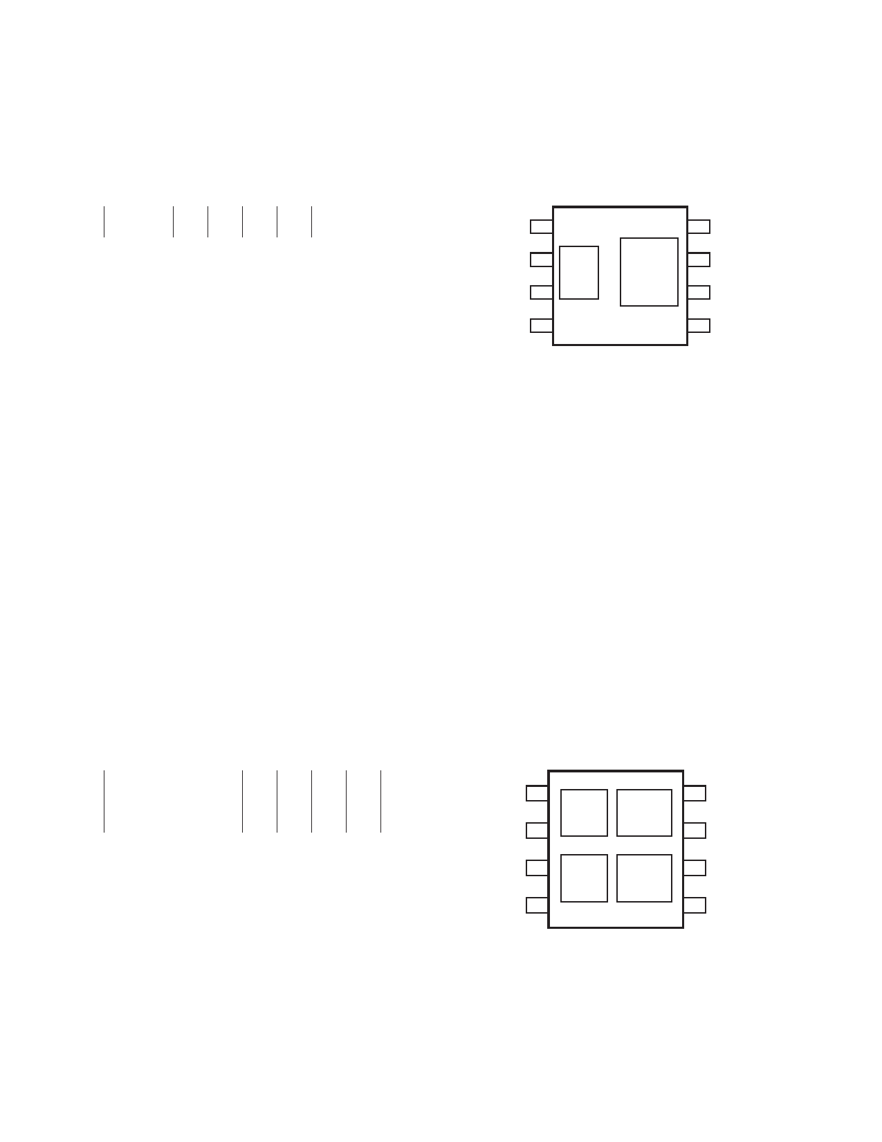
Thermal Resistance Model for ACPL-K44T
The diagram of ACPL-K44T for measurement is shown in Figure 16. Here, one die is heated first and the temperatures of
all the dice are recorded after thermal equilibrium is reached. Then, the 2nd ,3rd and 4th die is heated and all the dice
temperatures are recorded. With the known ambient temperature, the die junction temperature and power dissipation,
the thermal resistance can be calculated. The thermal resistance calculation can be cast in matrix form. This yields a 4 by
4 matrix for our case of two heat sources.
R11 R12 R13 R14
P1
T1
R21 R22 R23 R24
R31 R32 R33 R34
X
P2
P3
=
T2
T3
R41 R42 R43 R44
P4
T4
R11 : Thermal Resistance of Die1 due to heating of Die1 (˚C/W)
R12 : Thermal Resistance of Die1 due to heating of Die2 (˚C/W)
R13 : Thermal Resistance of Die1 due to heating of Die3 (˚C/W)
R14 : Thermal Resistance of Die1 due to heating of Die4 (˚C/W)
R21 : Thermal Resistance of Die2 due to heating of Die1 (˚C/W)
R22 : Thermal Resistance of Die2 due to heating of Die2 (˚C/W)
R23 : Thermal Resistance of Die2 due to heating of Die3 (˚C/W)
R24 : Thermal Resistance of Die2 due to heating of Die4 (˚C/W)
1
8
Die1:
Die2:
LED 1 Detector 1
2
7
3
Die3:
Die4:
6
LED 1 Detector 2
4
5
Figure 16. Diagram of ACPL-K44T for measurement
10
Share Link: 