ACPL-064L-000E 查看數據表(PDF) - Avago Technologies
零件编号
产品描述 (功能)
生产厂家
ACPL-064L-000E Datasheet PDF : 16 Pages
| |||
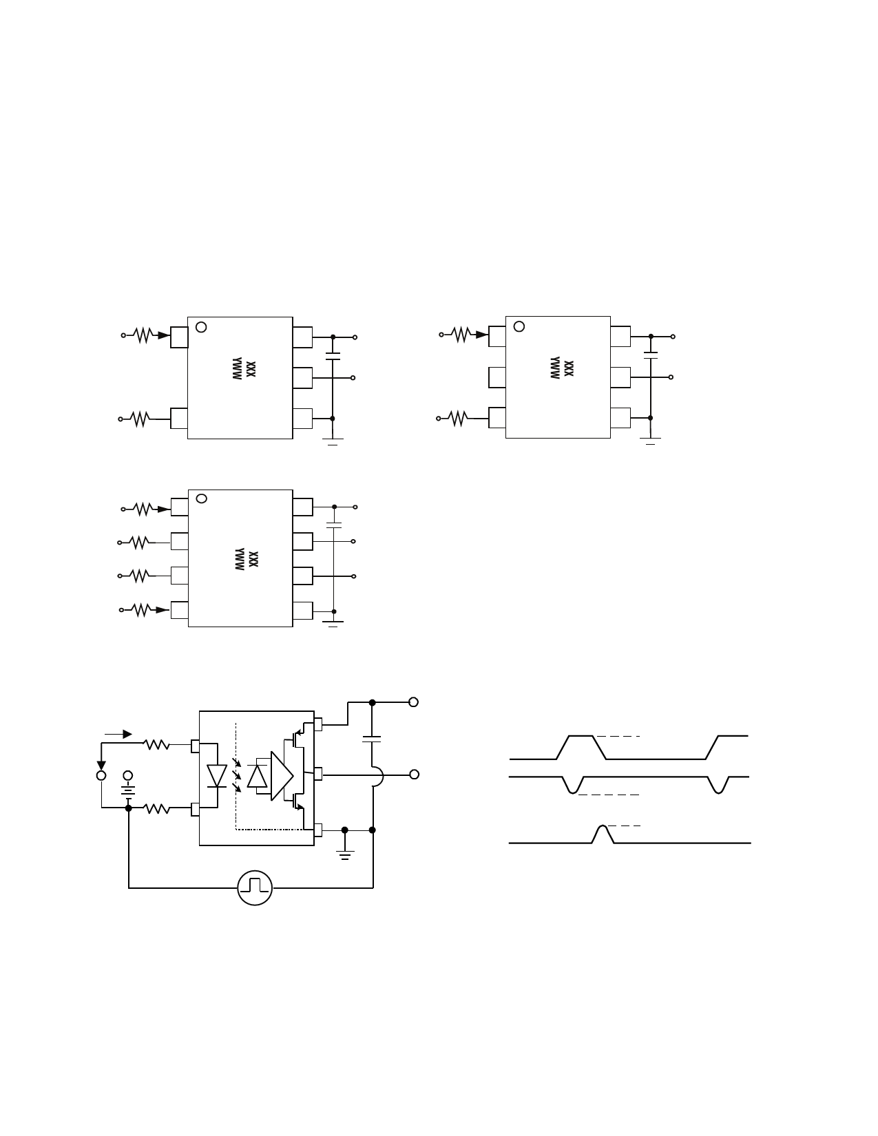
Supply Bypassing, LED Bias Resistors and PC Board Layout
The ACPL-x6xL optocouplers are extremely easy to use
and feature high speed, push-pull CMOS outputs. Pull-up
resistors are not required.
The external components required for proper operation
are the input limiting resistors and the output bypass
capacitor. Capacitor values should be 0.1 µF.
For each capacitor, the total lead length connecting the
capacitor to the VDD and GND pins should not exceed
20 mm.
For ACPL-M61L/W61L:
VDD = 3.3 V: R1 = 510 Ω ± 1%, R2 = 360 Ω ± 1%
VDD = 5.0 V: R1 = 1000 Ω ± 1%, R2 = 680 Ω ± 1%
RT = R1 + R2 R1/R2 ≈ 1.5
For ACPL-064L/K64L:
VDD = 3.3 V: R1 = 430 Ω ± 1%, R2 = 430 Ω ± 1%
VDD = 5.0 V: R1 = 845 Ω ± 1%, R2 = 845 Ω ± 1%
RT = R1 + R2 R1/R2 ≈ 1
R1 IF
VI
1
6
5
R2
GND1
3
4
ACPL-M61L
VDD
C = 0.1µF
Vo
GND2
R1 IF
VI
1
2
R2
GND1
3
6
5
4
ACPL-W61L
VDD
C = 0.1µF
Vo
GND2
VI R1 IF 1
8
R2
GND1
2
7
R2
GND2
3
6
VI R1 IF 4
5
ACPL-064L/K64L
VDD
C = 0.1µF
Vo1
Vo2
GND2
3.3V / 5V
VDD
IF
C = 0.1µF
V CM
VCM (PEAK)
A
B
Anode
Vo
Output
Monitoring
0V
VO VDD SWITCH AT A: IF = 0 mA
VO (min.)
CM H
node
SWITCH AT B: I F= 2 mA
Cathode
Shield
GND
VO
V O (max.)
GND
CM L
VCM
Pulse Gen +
−
Figure 8. Recommended printed circuit board layout and input current limiting resistor selection.
10
Share Link: 