ACT6311 查看數據表(PDF) - Active-Semi, Inc
零件编号
产品描述 (功能)
生产厂家
ACT6311 Datasheet PDF : 11 Pages
| |||
ACT6311
Rev 4, 15-Nov-12
LOGIC
LED1
ACT6311
FB
R2
LED2
LED3
R1
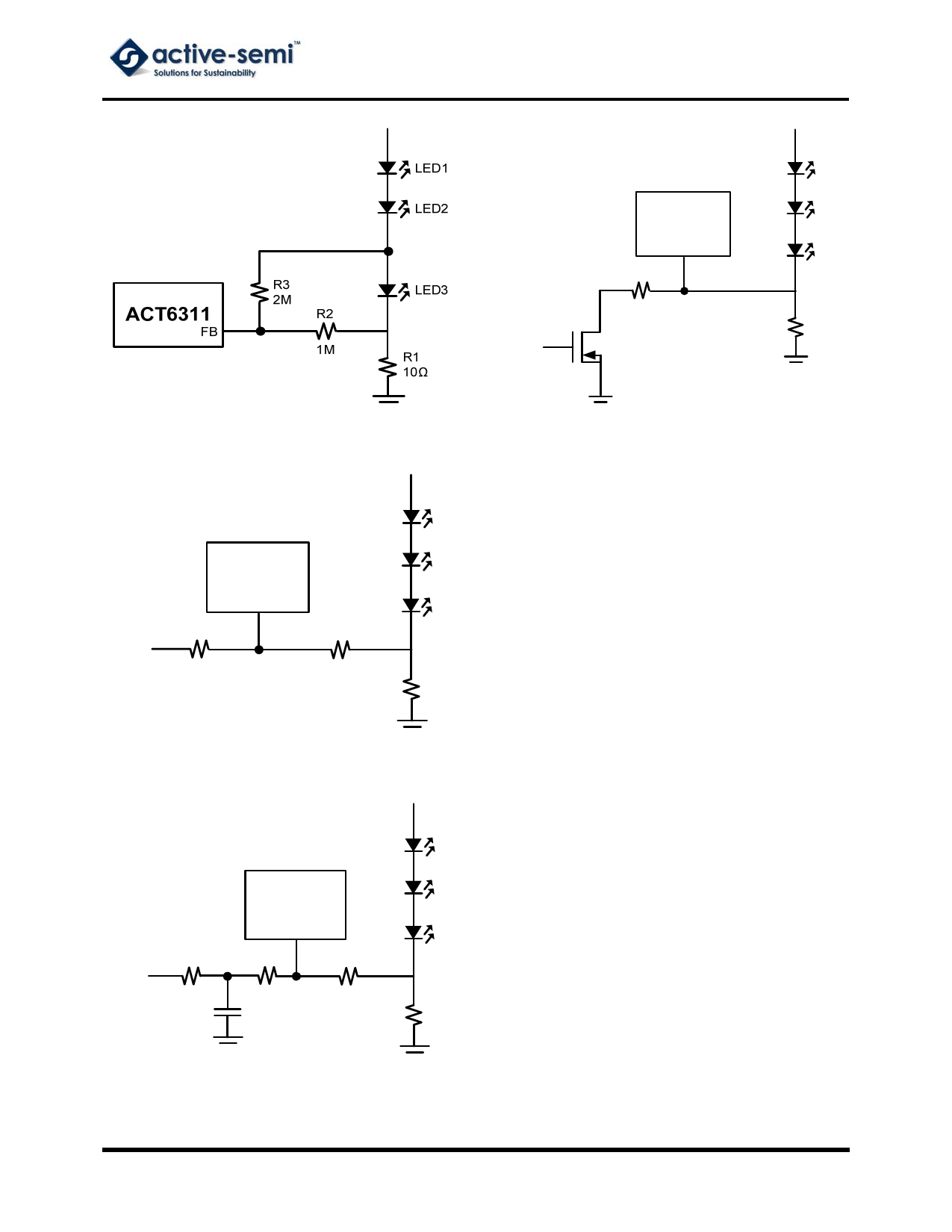
Figure 4. Current Setting for White LED Application
LED1
LED2
ACT6311
FB
LED3
R3
R2
VDC
33.4k
56k
R1
62Ω
Figure 5. DC Voltage Controlled Dimming
R4
PWM
10k
LED1
LED2
ACT6311
FB
LED3
R3
R2
33.4k
56k
C1
R1
0.1µF
62Ω
Figure 7. Logic Controlled Dimming
Start-up and Inrush Current
In order to facilitate quick startup, a soft-start circuit
is not incorporated into the ACT6311. When the IC
is first turned on with no external soft-start circuit,
the peak inrush current is about 400mA. Figure 8
shows an implementation for soft-start. When
soft-start and dimming controls are used
simultaneously, a low frequency PWM signal (less
than 10kHz) or the methods in Figures 5, 6 and 7
should be used.
Open-Circuit Protection (White LEDs)
If one of the LEDs is disconnected, the FB voltage
drops to zero and the IC switches at maximum duty
cycle. This results in a high voltage that may
exceed the SW voltage rating. To limit this voltage,
use a Zener diode as shown in Figure 9. The Zener
voltage must be large than the total forward voltage
of the LEDs and the current rating should be higher
than 0.1mA.
Board Layout
To reduce EMI, minimize the area and path length
of all traces connected to SW. Use a ground plane
under the switching regulator and connect R1
directly to the G pin of the IC.
Figure 6. Filtered PWM Controlled Dimming
Innovative PowerTM
-6-
www.active-semi.com
Copyright © 2012 Active-Semi, Inc.
Share Link: 