AD6122ACP 查看數據表(PDF) - Analog Devices
零件编号
产品描述 (功能)
生产厂家
AD6122ACP Datasheet PDF : 20 Pages
| |||
AD6122
FROM EXTERNAL
VOLTAGE REGULATOR
AD6122
LDOE
LDOB
LDOC
REFOUT
1.23V
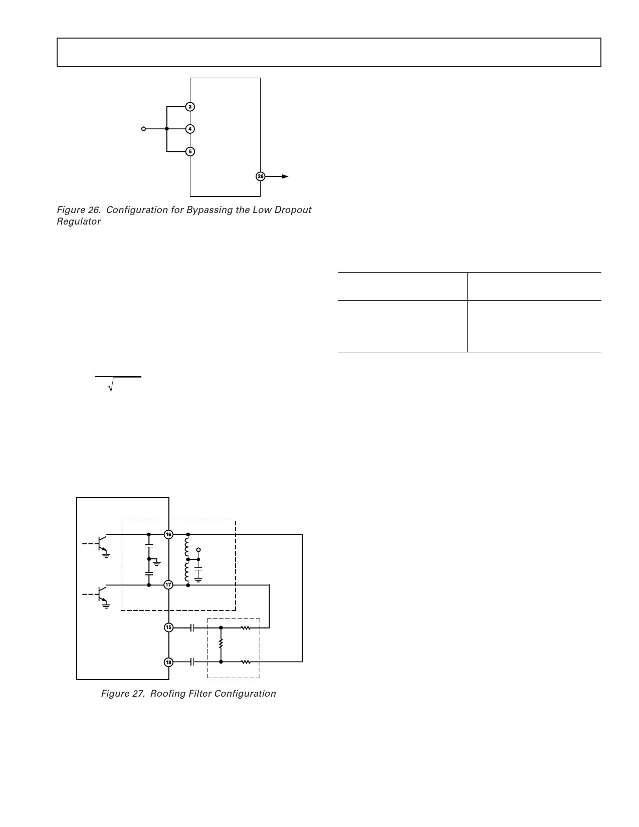
Figure 26. Configuration for Bypassing the Low Dropout
Regulator
ROOFING FILTER
Because the outputs of the AD6122 modulator are open collec-
tor, the parasitic capacitances seen at the output of the modula-
tor, and inputs of the IF amplifiers, are high enough to create a
low-pass filter, which may attenuate the IF signal. Consequently,
the parasitic capacitance must be cancelled by using external
inductors to form a parallel resonant circuit. The external in-
ductors and the internal parasitic capacitors form what is known
as the roofing filter, with the resonant frequency given by
Equation 2.
f0 =
1
2 π LCPAR
(2)
where f0 is the IF frequency, in Hertz, CPAR is the total parasitic
capacitance in Farads, and L is the value of external inductors,
in henrys.
The roofing filter may be composed of the pull-up inductors
required on the open collector outputs of the I and Q modula-
tor. This configuration is shown in Figure 27. The 10 nF ca-
pacitors are used for ac coupling.
AD6122
MODOPP
2CPAR
L/2 VCC
2CPAR
MODOPN
IFINN
L/2
10nF
PARALLEL
RESONANT
CIRCUIT
10nF
IFINP
10nF ATTENUATOR
Figure 27. Roofing Filter Configuration
The attenuator is discussed in the next section entitled Measur-
ing Adjacent Channel Protection Ratio (ACPR).
In order to confirm whether the roofing filter has been correctly
designed, sweep the LO frequency and view the output of the IF
amplifier on a spectrum analyzer. The signal should peak at the
IF frequency if the inductor value is correct. The Q of the filter
should be low enough so that variations in the parasitic capaci-
tances should be negligible.
The value of inductor required will be a function of the IF fre-
quency at which we are operating. The values of inductors used
during characterization at Analog Devices are shown in Table
II. Because the exact value will also be a function of printed
circuit board layout, we will have to vary the value from those in
Table II to those required for our board.
Table II. Roofing Filter Inductor Values
IF Frequency (MHz)
50–125
126–200
201–275
276–350
Value of Roofing Filter
Inductor (nH)
470
150
68
27
It should be noted that the roofing filter is only required when
cascading the output from the I/Q modulator to the input of the
IF amplifiers. If we are driving into the IF amplifiers directly, no
roofing filter is required, however, pull-up inductors are required
in order to set the dc voltage of the open collector modulator
outputs.
MEASURING ADJACENT CHANNEL POWER RATIO
(ACPR)
At maximum IF gain and specified input conditions (500 mV
p-p baseband inputs), the output of the I/Q modulator is 11 dB
greater than the P1 dB (one dB compression point) of the IF
amplifiers. This configuration maximizes the ratio of signal to
LO feedthrough and also maximizes the signal to noise ratio.
Once these ratios are maximized, we can attenuate the noise,
signal and LO feedthrough without affecting the ratios. There-
fore, attenuation is required between the I/Q modulator and the
IF amplifiers.
In order to determine exactly how much attenuation is required,
we must recognize that ACPR is a function of the attenuation
from the modulator outputs to the IF amplifier inputs. As a
result, in order to determine how much attenuation is required,
we must first know how good an ACPR performance is desired.
If too much attenuation is applied, the ACPR will be very good,
but, the IF amplifier’s output power level will be low, possibly
resulting in poor signal to noise ratio and possibly requiring
additional amplification external to the AD6122.
An appropriate method that can be used to provide the correct
amount of attenuation between the modulator outputs and the
IF amplifier inputs is a simple differential voltage divider. The
topology and its design equations are shown in Figure 28 and
Equations 3 and 4. The input impedance of the IF amplifiers is
typically 1 kΩ. As a result, if we design resistor R2 to be much
less than 1 kΩ, we can neglect the effects of the IF amplifier’s
input impedance on the attenuator.
REV. B
–13–
Share Link: 