AD7414ART-0REEL жҹҘзңӢж•ёж“ҡиЎЁпјҲPDFпјү - Analog Devices
йӣ¶д»¶зј–еҸ·
дә§е“ҒжҸҸиҝ° (еҠҹиғҪ)
з”ҹдә§еҺӮ家
AD7414ART-0REEL Datasheet PDF : 20 Pages
| |||
AD7414/AD7415
Parameter
SDA Low Setup Time to SCL Low
(Start Condition), t4
SDA High Hold Time after SCL High
(Stop Condition), t5
SDA and SCL Fall Time, t6
Power-Up Time
A Version
50
50
90
4
Unit Test Conditions/Comments
ns min See Figure 2
ns min See Figure 2
ns max See Figure 2
Вөs typ
1 Accuracy specifications apply only to voltages listed under Test Conditions. See Temperature Accuracy vs. Supply section for typical accuracy performance over the
full VDD supply range.
2 100% production tested at 40В°C to these limits.
3 These current values can be used to determine average power consumption at different one-shot conversion rates. Average power consumption at the automatic
conversion rate of 1.25 kHz is 940 ВөW.
4 This peak supply current is required for 29 Вөs (the conversion time plus power-up time) out of every 800 Вөs (the conversion rate).
5 These current values are derived by not issuing a stop condition at the end of a write or read, thus preventing the part from going into a conversion.
6 The current is derived assuming a 400 kHz serial clock being active continuously.
7 On power-up, the initial input current, IIN, on the AS pin is typically 50 ВөA.
8 The SDA and SCL timing is measured with the input filters turned on so as to meet the fast mode I2C specification. Switching off the input filters improves the transfer
rate but has a negative effect on the EMC behavior of the part.
9 Guaranteed by design. Not tested in production.
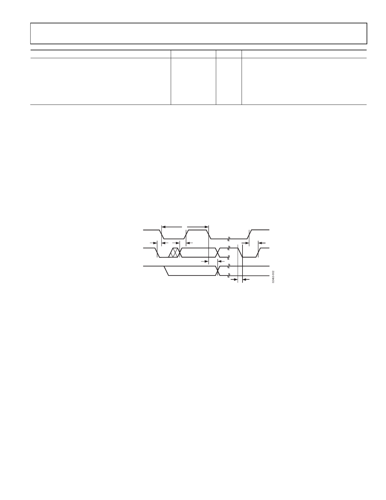
SCL
SDA
DATA IN
SDA
DATA OUT
t1
t4
t2
t5
t3
t6
Figure 2. Diagram for Serial Bus Timing
Rev. E | Page 4 of 20
Share Link: 