AD779 查看數據表(PDF) - Analog Devices
零件编号
产品描述 (功能)
生产厂家
AD779 Datasheet PDF : 12 Pages
| |||
AD779
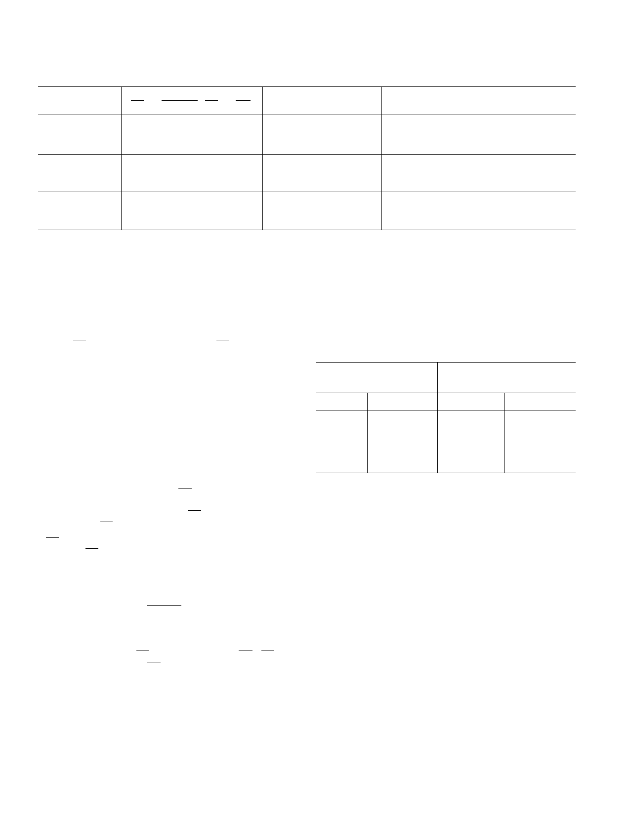
CONVERSION TRUTH TABLE
Mode
INPUTS
SC EOCEN CS OE
Start Conversion
1
X
f
X
0
X
Conversion Status X 0
X0
X1
Data Access
XX
XX
XX
XX
XX
XX
XX
XX
XX
X1
1
X
0
0
NOTES
1 = HIGH voltage level.
0 = LOW voltage level.
X = Don’t care.
f = HIGH to LOW transition. Must stay LOW for t = tCP.
OUTPUTS
EOC DB13 . . . DB0 Status
0
1
High Z
High Z
High Z
MSB . . . LSB
No Conversion
Start Conversion
Continuous Conversion (Not Recommended)
Converting
Not Converting
Either
Three-State
Three-State
Data Out
CONVERSION CONTROL
Before a conversion is started, End-of-Convert (EOC) is HIGH
and the sample-hold is in track mode. A conversion is started by
bringing SC LOW, regardless of the state of CS.
After a conversion is started, the sample-hold goes into hold
mode and EOC goes LOW, signifying that a conversion is in
progress. During the conversion, the sample-hold will go back
into track mode and start acquiring the next sample.
In track mode, the sample-hold will settle to ± 0.003% (14 bits)
in 1.5 µs maximum. The acquisition time does not affect the
throughput rate as the AD779 goes back into track mode more
than 2 µs before the next conversion. In multichannel systems,
the input channel can be switched as soon as EOC goes LOW if
the maximum throughput rate is needed.
When EOC goes HIGH, the conversion is completed and the
output data may be read. Bringing OE LOW makes the output
register contents available on the output data bits (DB13–DB0).
A period of time tCD is required after OE is brought HIGH
before the next SC instruction is issued.
If SC is held LOW, conversion accuracy may deteriorate. For
this reason, SC should not be held low in any attempt to operate
in a continuously converting mode.
END-OF-CONVERT
End-of-Convert (EOC) is a three-state output which is enabled
by End-of-Convert Enable EOCEN.
OUTPUT ENABLE OPERATION
The data bits (DB13–DB0) are three-state outputs that are
enabled by Chip Select (CS) and Output Enable (OE). CS
should be LOW tOE before OE is brought LOW. The output is
read in a single cycle as a 14-bit word.
In unipolar mode (BIPOFF tied to AGND), the output coding
is straight binary. In bipolar mode (BIPOFF tied to REFOUT),
output coding is twos complement binary.
POWER-UP
The AD779 typically requires 10 µs after power-up to reset
internal logic
14-BIT MODE CODING FORMAT (1 LSB = 0.61 mV)
Unipolar Coding
(Straight Binary)
Bipolar Coding
(Twos Complement)
VIN
0.00000 V
5.00000 V
9.99939 V
Output Code
000 . . . 0
100 . . . 0
111 . . . 1
VIN
–5.00000 V
–0.00061 V
0.00000 V
+2.50000 V
+4.99939 V
Output Code
100 . . . 0
111 . . . 1
000 . . . 0
010 . . . 0
011 . . . 1
Application Information
INPUT CONNECTIONS AND CALIBRATION
The high (10 MΩ) input impedance of the AD779 eases the
task of interfacing to high source impedances or multiplexer
channel-to-channel mismatches of up to 300 Ω. The 10 V p-p
full-scale input range accepts the majority of signal voltages
without the need for voltage divider networks which could
deteriorate the accuracy of the ADC.
The AD779 is factory trimmed to minimize offset, gain and
linearity errors. In unipolar mode, the only external component
that is required is a 50 Ω ± 1% resistor. Two resistors are
required in bipolar mode. If offset and gain are not critical, even
these components can be eliminated.
In some applications, offset and gain errors need to be more
precisely trimmed. The following sections describe the correct
procedure for these various situations.
–8–
REV. B
Share Link: 