AD7818ARM-REEL 查看數據表(PDF) - Analog Devices
零件编号
产品描述 (功能)
生产厂家
AD7818ARM-REEL Datasheet PDF : 20 Pages
| |||
Data Sheet
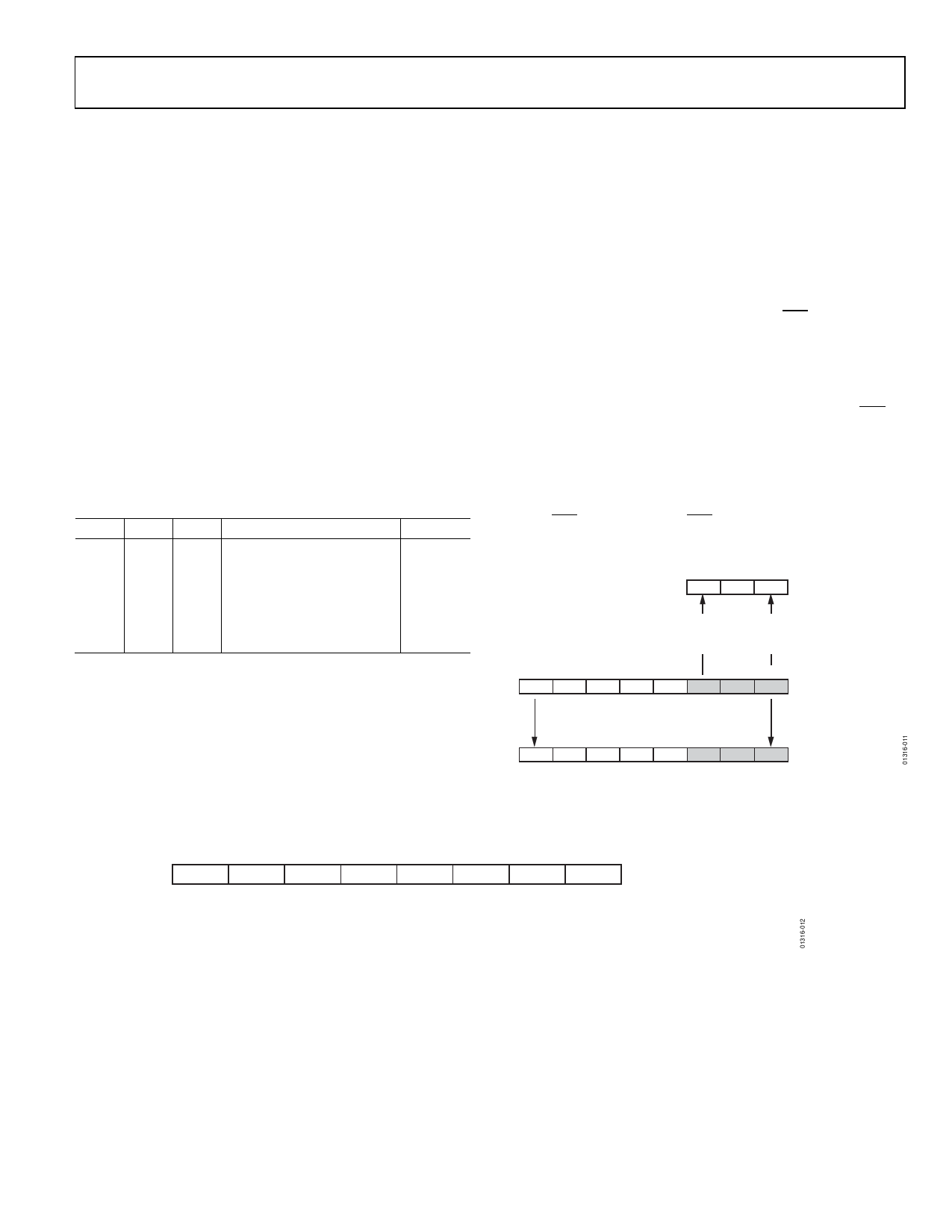
CONTROL BYTE
The AD7817/AD7818 contain two on-chip registers, the address
register and the overtemperature register. These registers can be
accessed by carrying out an 8-bit serial write operation to the devices.
The 8-bit word or control byte written to the AD7817/AD7818 is
transferred to one of the two on-chip registers as follows.
Address Register
If the five MSBs of the control byte are logic zero, the three LSBs
of the control byte are transferred to the address register (see
Figure 6). The address register is a 3-bit-wide register used to
select the analog input channel on which to carry out a conversion.
It is also used to select the temperature sensor, which has the 000
address. Table 6 shows the channel selection. The internal reference
selection connects the input of the ADC to a band gap reference.
When this selection is made and a conversion is initiated, the ADC
output must be approximately midscale. After power-up, the
default channel selection is DB2 = DB1 = DB0 = 0 (temperature
sensor).
Table 6. Channel Selection
DB2 DB1 DB0 Channel Selection
0
0
0
Temperature sensor
0
0
1
Channel 1
0
1
0
Channel 2
0
1
1
Channel 3
1
0
0
Channel 4
1
1
1
Internal reference (1.23 V)
Device
All
All
AD7817
AD7817
AD7817
All
AD7817/AD7818
Overtemperature Register
If any of the five MSBs of the control byte are logic one, the entire
eight bits of the control byte are transferred to the overtemperature
register (see Figure 6). At the end of a temperature conversion,
a digital comparison is carried out between the 8 MSBs of the
temperature conversion result (10 bits) and the contents of the
overtemperature register (8 bits). If the result of the temperature
conversion is greater than the contents of the overtemperature
register (OTR), the overtemperature indicator (OTI) goes logic
low. The resolution of the OTR is 1°C. The lowest temperature
that can be written to the OTR is −95°C and the highest is
+152°C (see Figure 7). However, the usable temperature range of
the temperature sensor is −55°C to +125°C. Figure 7 shows the
OTR and how to set TALARM (the temperature at which the OTI
goes low).
OTR (Dec) = TALARM (°C) + 103°C
For example, to set TALARM to 50°C, OTR = 50 + 103 = 153 Dec
or 10011001 bin. If the result of a temperature conversion exceeds
50°C, OTI goes logic low. The OTI logic output is reset high at the
end of a serial read operation or if a new temperature measurement
is lower than TALARM. The default power on TALARM is 50°C.
DB2 DB1 DB0 ADDRESS REGISTER
IF ANY BIT DB7 TO DB3 ARE LOGIC 0
THEN DB2 TO DB0 ARE WRITTEN TO
THE ADDRESS REGISTER
MSB
LSB
DB7 DB6 DB5 DB4 DB3 DB2 DB1 DB0 CONTROL BYTE
DB7
IF ANY BIT DB7 TO DB3 IS SET TO A
LOGIC 1, THEN THE FULL 8 BITS OF THE
CONTROL WORD ARE WRITTEN TO THE
OVERTEMPERATURE REGISTER
DB6 DB5 DB4 DB3 DB2 DB1
DB0
OVERTEMPERATURE
REGISTER (OTR)
Figure 6. Address and Overtemperature Register Selection
OVERTEMPERATURE REGISTER
MSB
LSB
DB7
DB6
DB5
DB4
DB3
DB2
DB1
DB0
0
0
0
0
1
0
0
0
1
1
1
1
1
1
1
1
OVERTEMPERATURE REGISTER (DEC) = TALARM + 103°C
TALARM RESOLUTION = 18/LSB
Figure 7. The Overtemperature Register (OTR)
MINIMUM TEMPERATURE = –95°C
MAXIMUM TEMPERATURE = +152°C
Rev. D | Page 11 of 20
Share Link: 