AD8222-EVAL 查看數據表(PDF) - Analog Devices
零件编号
产品描述 (功能)
生产厂家
AD8222-EVAL Datasheet PDF : 24 Pages
| |||
AD8222
+
10µF
0.1µF
100pF
NPO
1kΩ 5%
+IN
1000pF
1kΩ
–IN
100pF
NPO
5%
10µF + 0.1µF
+12V
+5V
0.1µF
AD8222
(DIFF OUT)
+OUT 1kΩ
1kΩ
–OUT
REF2
+IN2
+5V REF
–12V
2200pF
2200pF
VDD
IN+
AD7688
IN–
GND REF
0.1µF
+12V
10µF
X5R
VIN
VOUT
ADR435
GND
+5V REF
0.1µF
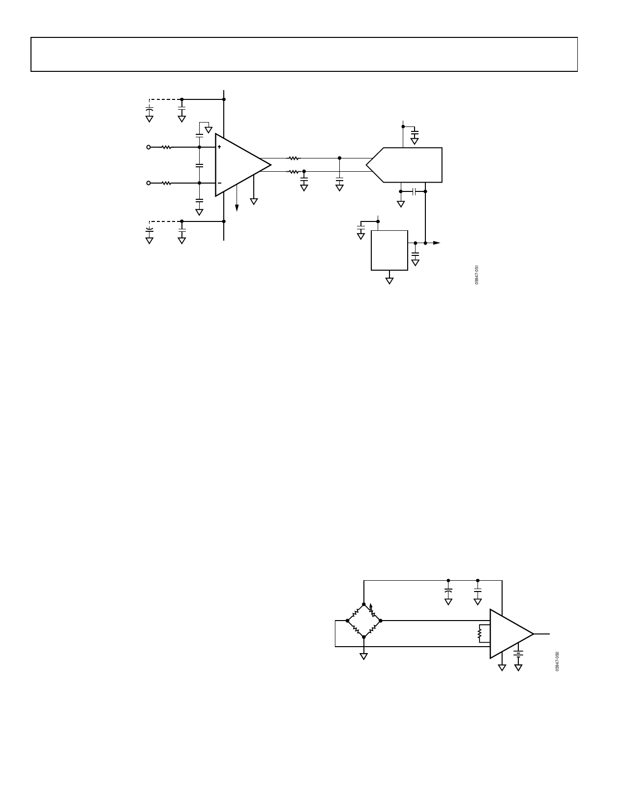
Figure 51. Driving a Differential ADC
DRIVING A DIFFERENTIAL INPUT ADC
The AD8222 can be configured in differential output mode
to drive a differential analog-to-digital converter. Figure 51
illustrates several of the concepts.
First Antialiasing Filter
The 1 kΩ resistor, 1000 pF capacitor, and 100 pF capacitors in
front of the in-amp form a 76 kHz filter. This is the first of two
antialiasing filters in the circuit and helps to reduce the noise of
the system. The 100 pF capacitors protect against common-
mode RFI signals. Note that they are 5% COG/NPO types.
These capacitors match well over time and temperature, which
keeps the system’s CMRR high over frequency.
Second Antialiasing Filter
A 1 kΩ resistor and 2200 pF capacitor are located between each
AD8222 output and ADC input. They create a 72 kHz low-pass
filter for another stage of antialiasing protection.
These four elements also help distortion performance. The
2200 pF capacitor provides charge to the switched capacitor
front end of the ADC, while the 1 kΩ resistor shields the
AD8222 from driving any sharp current changes. If the
application requires a lower frequency antialiasing filter and is
distortion sensitive, increase the value of the capacitor rather
than the resistor.
The 1 kΩ resistors can also protect an ADC from overvoltages.
Because the AD8222 runs on wider supply voltages than a
typical ADC, there is a possibility of overdriving the ADC. This
is not an issue with a PulSAR® converter, such as the AD7688.
Its input can handle a 130 mA overdrive, which is much higher
than the short-circuit limit of the AD8222. However, other
converters have less robust inputs and may need the added
protection.
Reference
The ADR435 supplies a reference voltage to both the ADC and
the AD8222. Because REF2 on the AD8222 is grounded, the
common-mode output voltage is precisely half the reference
voltage, exactly where it needs to be for the ADC.
PRECISION STRAIN GAUGE
The low offset and high CMRR over frequency of the
AD8222 make it an excellent candidate for both ac and dc
bridge measurements. As shown in Figure 52, the bridge can
be connected to the inputs of the amplifier directly.
5V
10µF 0.1µF
350Ω
350Ω
350Ω
350Ω
+IN +
RG AD8222
–
–IN
2.5V
Figure 52. Precision Strain Gauge
Rev. 0 | Page 20 of 24
Share Link: 