ADM561JRSZ-REEL 查看數據表(PDF) - Analog Devices
零件编号
产品描述 (功能)
生产厂家
ADM561JRSZ-REEL
Analog Devices

ADM561JRSZ-REEL Datasheet PDF : 12 Pages
| |||
ADM560/ADM561
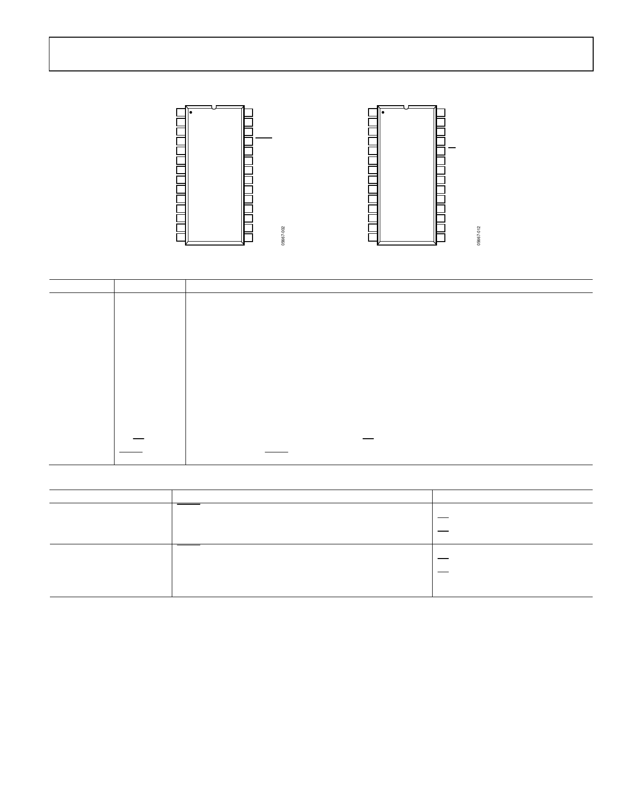
PIN CONFIGURATION AND FUNCTION DESCRIPTIONS
T3OUT 1
T1OUT 2
T2OUT 3
R2IN 4
R2OUT 5
T2IN 6
T1IN 7
R1OUT 8
R1IN 9
GND 10
VCC 11
C1+ 12
V+ 13
C1– 14
ADM560
TOP VIEW
(Not to Scale)
28 T4OUT
27 R3IN
26 R3OUT
25 SHDN
24 EN
23 R4IN
22 R4OUT
21 T4IN
20 T3IN
19 R5OUT
18 R5IN
17 V–
16 C2–
15 C2+
Figure 2.ADM560 Pin Configuration
T3OUT 1
T1OUT 2
T2OUT 3
R2IN 4
R2OUT 5
T2IN 6
T1IN 7
R1OUT 8
R1IN 9
GND 10
VCC 11
C1+ 12
V+ 13
C1– 14
ADM561
TOP VIEW
(Not to Scale)
28 T4OUT
27 R3IN
26 R3OUT
25 SHDN
24 EN
23 R4IN
22 R4OUT
21 T4IN
20 T3IN
19 R5OUT
18 R5IN
17 V–
16 C2–
15 C2+
Figure 3. ADM561 Pin Configuration
Table 3. Pin Function Descriptions
Pin No.
Mnemonic
Description
2, 3, 1, 28
T1OUT to T4OUT
9, 4, 27, 23, 18 R1IN to R5IN
Transmitter (Driver) Outputs. Typically ±6 V.
Receiver Inputs. These inputs accept RS-232 signal levels. An internal 5 kΩ pull-down resistor to GND is
connected on each of these inputs.
8, 5, 26, 22, 19 R1OUT to R5OUT
7, 6, 20, 21
T1IN to T4IN
10
GND
Receiver Outputs. These are 3 V logic levels.
Transmitter (Driver) Inputs. These inputs accept 3 V or 5 V logic levels. An internal 400 kΩ pull-up resistor
to VCC is connected on each input.
Ground Pin. Must be connected to 0 V.
11
VCC
Power Supply Input 3.3 V ± 10%.
12, 14
C1+, C1−
External Capacitor 1 is connected between these pins.
13
V+
Internally Generated Positive Supply. +6.6 V nominal.
15, 16
C2+, C2−
External Capacitor 2 is connected between these pins.
17
V−
Internally Generated Negative Supply. −6.6 V nominal.
24
EN/EN
Receiver Enable. EN, active high on ADM560. EN, active low on ADM561. Refer to Table 4.
25
SHDN/SHDN Shutdown Control. SHDN, active low on ADM560. SHDN, active high on ADM561. Refer to Table 4.
Table 4. ADM560/ADM561 Enable and Shutdown Control
ADM560
Normal Operation
SHDN = 1
EN = 1; receivers active
EN = 0; receivers inactive
Shutdown Mode
SHDN = 0
EN = 1; Receiver R1 to Receiver R3 inactive
EN = 1; Receiver R4 and Receiver R5 active
EN = 0; Receiver R1 to Receiver R5 inactive
ADM561
SHDN = 0
EN = 0; receivers active
EN = 1; receivers inactive
SHDN = 1
EN = 0; receivers inactive
EN = 1; receivers inactive
Rev. B | Page 5 of 12
Share Link: