ADT7475 ТЪЦуюІТЋИТЊџУАе№╝ѕPDF№╝Ѕ - ON Semiconductor
жЏХС╗Ху╝ќтЈи
С║ДтЊЂТЈЈУ┐░ (тіЪУЃй)
ућЪС║Дтјѓт«Х
ADT7475 Datasheet PDF : 58 Pages
| |||
ADT7475
Product Description
The ADT7475 is a complete thermal monitor and multiple
fan controller for any system requiring thermal monitoring
and cooling. The device communicates with the system via
a serial system management bus. The serial bus controller
has a serial data line for reading and writing addresses and
data (Pin 16), and an input line for the serial clock (Pin 1).
All control and programming functions for the ADT7475
are performed over the serial bus. In addition, a pin can be
reconfigured as an SMBALERT output to signal
outРѕњofРѕњlimit conditions.
Quick Comparison Between ADT7473 and ADT7475
Рђб The ADT7473 supports advanced dynamic TMIN
features while the ADT7475 does not.
Рђб Acoustic smoothing is improved on the ADT7475.
Рђб THERM can be selected as an output only on the
ADT7475.
Рђб The ADT7475 has two additional configuration
registers.
Рђб The ADT7475 has other minor register changes.
The ADT7475 is similar to the ADT7473 in that it is
powered by a supply no greater than 3.6 V. Exceeding this
specification results in irreversible damage to the ADT7475.
Signal pins (TACH/PWM) should be pulled up or clamped
to 3.6 V maximum. See the Specifications Section for more
information.
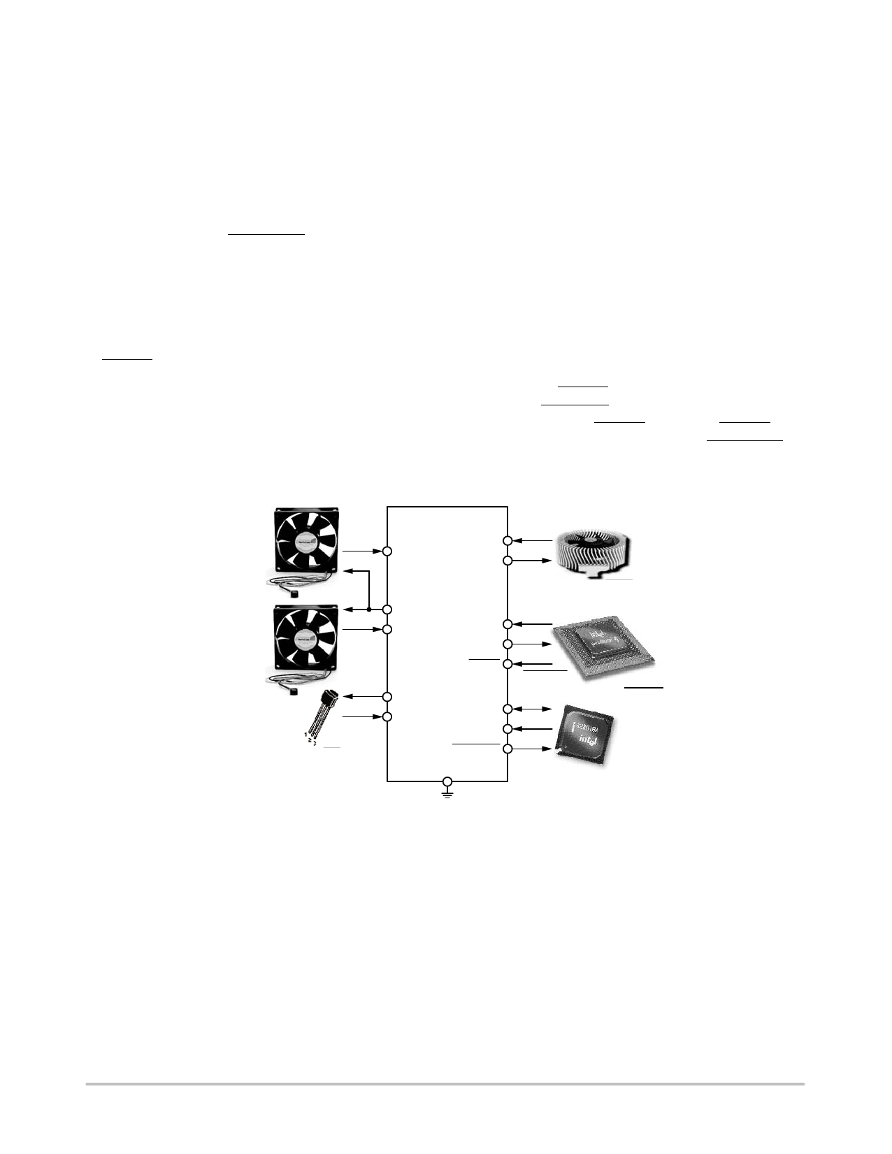
Recommended Implementation
Configuring the ADT7475 as shown in Figure 12 allows
the system designer to use the following features:
Рђб Two PWM outputs for fan control of upРѕњtoРѕњthree fans
(the front and rear chassis fans are connected in
parallel).
Рђб Three TACH fan speed measurement inputs.
Рђб VCC measured internally through Pin 3.
Рђб CPU temperature measured using the Remote 1
temperature channel.
Рђб Ambient temperature measured through the Remote 2
temperature channel.
Рђб Bidirectional THERM pin. This feature allows Intel
Pentium 4 PROCHOT monitoring and can function as
an overtemperature THERM output. The THERM pin
can alternatively be programmed as an SMBALERT
system interrupt output.
FRONT
CHASSIS
FAN
REAR
CHASSIS
FAN
AMBIENT
TEMPERATURE
ADT7475
TACH2
PWM1
TACH1
PWM3
TACH3
D2+
D2РђЊ
THERM
D1+
SDA
D1РђЊ
SCL
SMBALERT
GND
CPU FAN
PROCHOT
CPU
ICH
Figure 12. ADT7475 Configuration
Serial Bus Interface
On PCs and servers, control of the ADT7475 is carried out
using the SMBus. The ADT7475 is connected to this bus as
a slave device under the control of a master controller, which
is usually (but not necessarily) the ICH.
The ADT7475 has a fixed 7Рѕњbit serial bus address of
0101110 or 0x2E. The read/write bit must be added to get the
8Рѕњbit address (01011100 or 0x5C). Data is sent over the
serial bus in sequences of nine clock pulses, that is, eight bits
of data followed by an acknowledge bit from the slave
device. Transitions on the data line must occur during the
low period of the clock signal and remain stable during the
high period because a lowРѕњtoРѕњhigh transition when the clock
is high may be interpreted as a stop signal. The number of
data bytes that can be transmitted over the serial bus in a
single read or write operation is limited only by what the
master and slave devices can handle.
When all data bytes are read or written, stop conditions are
established. In write mode, the master pulls the data line high
during the tenth clock pulse to assert a stop condition.
In read mode, the master device overrides the acknowledge
bit by pulling the data line high during the low period before
the ninth clock pulse; this is known as no acknowledge. The
master takes the data line low during the low period before
http://onsemi.com
8
Share Link: 