ADUM2200BRWZ 查看數據表(PDF) - Analog Devices
零件编号
产品描述 (功能)
生产厂家
ADUM2200BRWZ Datasheet PDF : 20 Pages
| |||
ADuM2200/ADuM2201
DIN V VDE V 0884-10 (VDE V 0884-10) INSULATION CHARACTERISTICS
These isolators are suitable for reinforced electrical isolation only within the safety limit data. Maintenance of the safety data is ensured by
means of protective circuits. Note that the asterisk (*) branded on packages denotes DIN V VDE V 0884-10 approval for 846 V peak
working voltage.
Table 7.
Description
Installation Classification per DIN VDE 0110
For Rated Mains Voltage ≤ 300 V rms
For Rated Mains Voltage ≤ 450 V rms
For Rated Mains Voltage ≤ 600 V rms
Climatic Classification
Pollution Degree (DIN VDE 0110, Table 1)
Maximum Working Insulation Voltage
Input-to-Output Test Voltage, Method B1
Input-to-Output Test Voltage, Method A
After Environmental Tests Subgroup 1
After Input and/or Safety Test Subgroup 2
and Subgroup 3
Highest Allowable Overvoltage
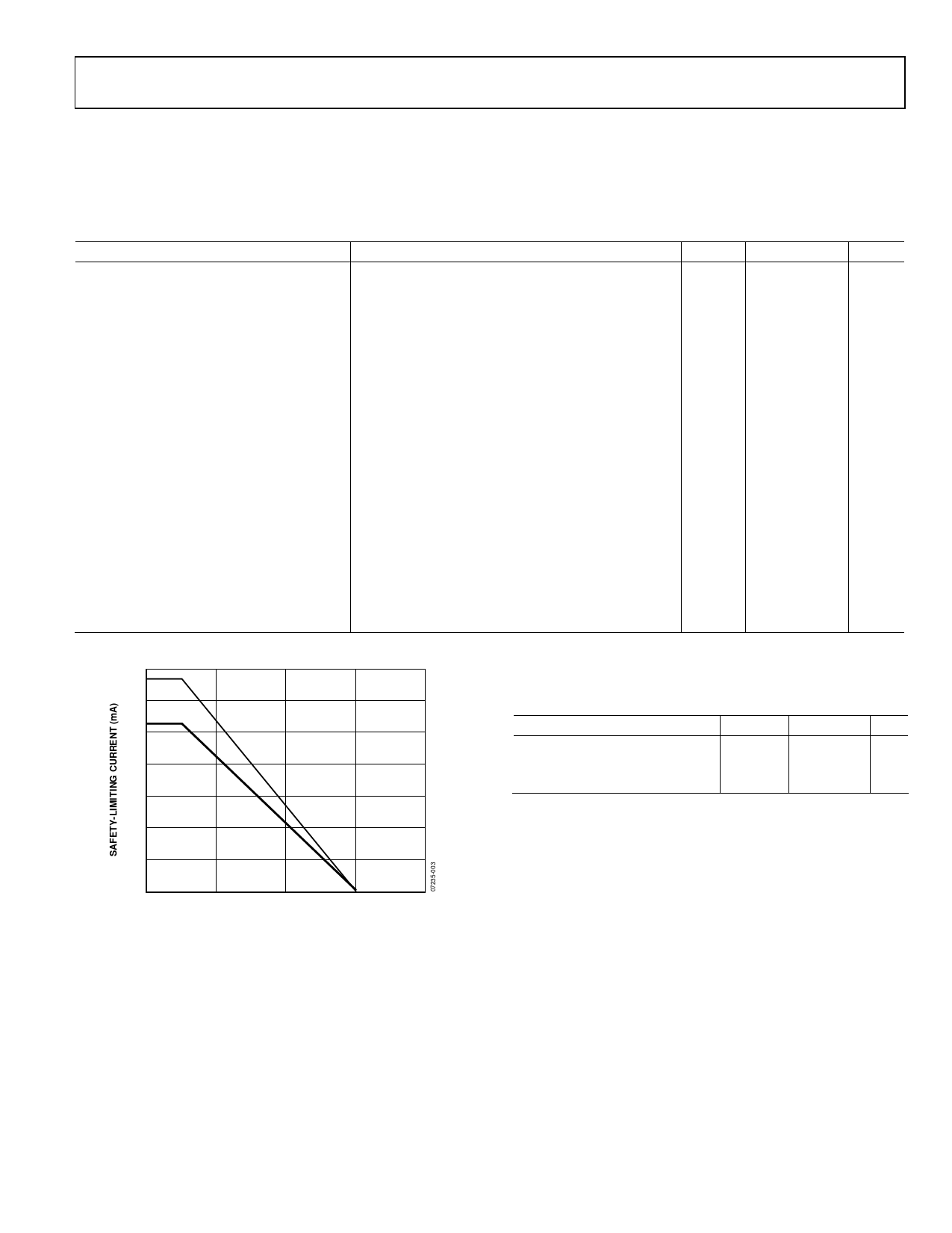
Safety-Limiting Values
Case Temperature
Side 1 Current
Side 2 Current
Insulation Resistance at TS
Conditions
VIORM × 1.875 = VPR, 100% production test, tm = 1 sec,
partial discharge < 5 pC
VIORM × 1.6 = VPR, tm = 60 sec, partial discharge < 5 pC
VIORM × 1.2 = VPR, tm = 60 sec, partial discharge < 5 pC
Transient overvoltage, tTR = 10 seconds
Maximum value allowed in the event of a failure;
see Figure 3
VIO = 500 V
Symbol Characteristic Unit
VIORM
VPR
VPR
VTR
I to IV
I to II
I to II
40/105/21
2
846
1590
1375
1018
6000
V peak
V peak
V peak
V peak
V peak
TS
150
°C
IS1
265
mA
IS2
335
mA
RS
>109
Ω
350
300
250
SIDE 2
200
150
SIDE 1
100
50
0
0
50
100
150
200
CASE TEMPERATURE (°C)
Figure 3. Thermal Derating Curve, Dependence of Safety Limiting
Values with Case Temperature per DIN V VDE V 0884-10
RECOMMENDED OPERATING CONDITIONS
Table 8.
Parameter
Operating Temperature
Supply Voltages1
Input Signal Rise and Fall Times
Symbol Min Max Unit
TA
−40 +105 °C
VDD1, VDD2 3.0 5.5 V
1.0 ms
1 All voltages are relative to their respective ground. See the DC Correctness
and Magnetic Field Immunity section for information on immunity to
external magnetic fields.
Rev. 0 | Page 11 of 20
Share Link: 