AFBR-5805Z 查看數據表(PDF) - Avago Technologies
零件编号
产品描述 (功能)
生产厂家
AFBR-5805Z
Avago Technologies

AFBR-5805Z Datasheet PDF : 14 Pages
| |||
Regulatory Compliance
These transceiver products are intended to enable com-
mercial system designers to develop equipment that
complies with the various international regulations gov-
erning certification of Information Technology Equip-
ment. See the Regulatory Compliance Table for details.
Additional information is available from your Avago Tech-
nologies sales representative.
Electrostatic Discharge (ESD)
There are two design cases in which immunity to ESD
damage is important.
The first case is during handling of the transceiver prior
to mounting it on the circuit board. It is important to
use normal ESD handling precautions for ESD sensitive
devices. These precautions include using grounded wrist
straps, work benches, and floor mats in ESD controlled
areas.
The second case to consider is static discharges to the
exterior of the equipment chassis containing the trans-
ceiver parts. To the extent that the duplex SC connector
is exposed to the outside of the equipment chassis it may
be subject to whatever ESD system level test criteria that
the equipment is intended to meet.
Electromagnetic Interference (EMI)
Most equipment designs utilizing these high speed trans-
ceivers from Avago Technologies will be required to meet
the requirements of FCC in the United States, CENELEC
EN55022 (CISPR 22) in Europe and VCCI in Japan.
These products are suitable for use in designs ranging
from a desktop computer with a single transceiver to a
concentrator or switch product with large number of
transceivers.
In all well-designed chassis, the two 0.5” holes required
for ST connectors to protrude through will provide 4.6 dB
more shielding than one 1.2” duplex SC rectangular
cutout. Thus, in a well-designed chassis, the duplex ST 1 x
9 transceiver emissions will be identical to the duplex SC
1 x 9 transceiver emissions.
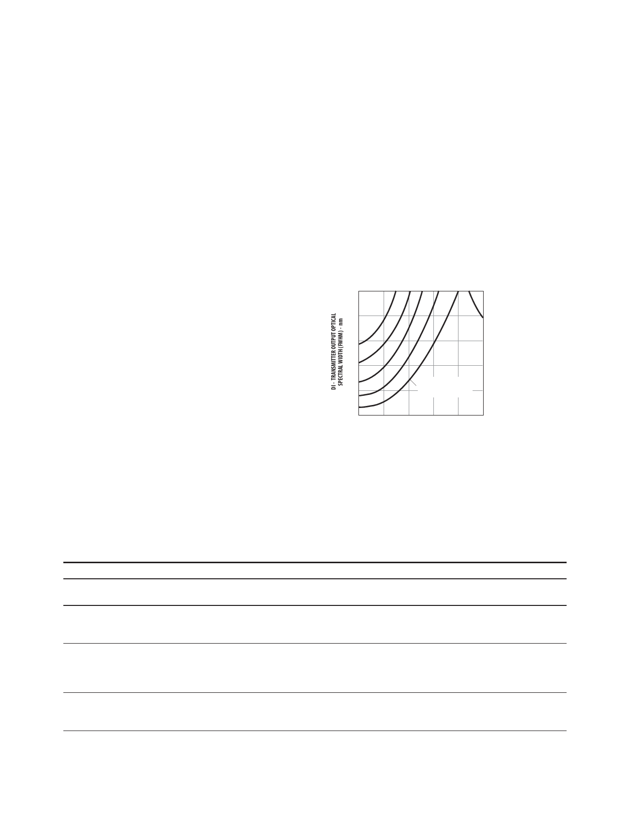
200
180
3.0
1.0
160
1.5
140 2.0
120 2.5
3.0
tr/f – TRANSMITTER
OUTPUT OPTICAL
RISE/FALL TIMES – ns
100
1260 1280 1300 1320 1340 1360
l C – TRANSMITTER OUTPUT OPTICAL RISE/FALL TIMES – ns
AFBR-5805 TRANSMITTER TEST RESULTS OF IC, DI AND
tr/f ARE CORRELATED AND COMPLY WITH THE ALLOWED
SPECTRAL WIDTH AS A FUNCTION OF CENTER WAVELENGTH
FOR VARIOUS RISE AND FALL TIMES.
Figure 9. Transmitter Output Optical Spectral Width (FWHM) vs.
Transmitter Output Optical Center Wavelength and Rise/Fall Times.
Regulatory Compliance Table
Feature
Electrostatic Discharge
(ESD) to the Electrical Pins
Electrostatic Discharge
(ESD) to the Duplex SC
Receptacle
Electromagnetic
Interference (EMI)
Immunity
Test Method
MIL-STD-883C
Method 3015.4
Variation of
IEC 801-2
FCC Class B
CENELEC CEN55022
Class B (CISPR 22B)
VCCI Class 2
Variation of IEC 61000-4-3
Performance
Class 2 (2000 to 3999 Volts)
Withstand up to 2200 V applied between electrical pins
Typically withstand at least 25 kV without damage when the Duplex
SC Connector Receptacle is contacted by a Human Body Model
probe.
Transceivers typically provide a 13 dB margin (with duplex SC
receptacle) or a 9 dB margin (with duplex ST receptacles) to the
noted standard limits. However, it should be noted that final margin
depends on the customer’s board and chassis design.
Typically show no measurable effect from a 10 V/m field swept from
10 to 450 MHz applied to the transceiver when mounted to a circuit
card without a chassis enclosure.
9
Share Link: