AM27C256-120JC 查看數據表(PDF) - Advanced Micro Devices
零件编号
产品描述 (功能)
生产厂家
AM27C256-120JC Datasheet PDF : 12 Pages
| |||
connection to all devices in the array and connected to
the READ line from the system control bus. This as-
sures that all deselected memory devices are in their
low-power standby mode and that the output pins are
only active when data is desired from a particular mem-
ory device.
System Applications
During the switch between active and standby condi-
tions, transient current peaks are produced on the ris-
ing and falling edges of Chip Enable. The magnitude of
these transient current peaks is dependent on the out-
put capacitance loading of the device. At a minimum, a
0.1 µF ceramic capacitor (high frequency, low inherent
inductance) should be used on each device between
VCC and VSS to minimize transient effects. In addition,
to overcome the voltage drop caused by the inductive
effects of the printed circuit board traces on EPROM ar-
rays, a 4.7 µF bulk electrolytic capacitor should be used
between VCC and VSS for each eight devices. The loca-
tion of the capacitor should be close to where the
power supply is connected to the array.
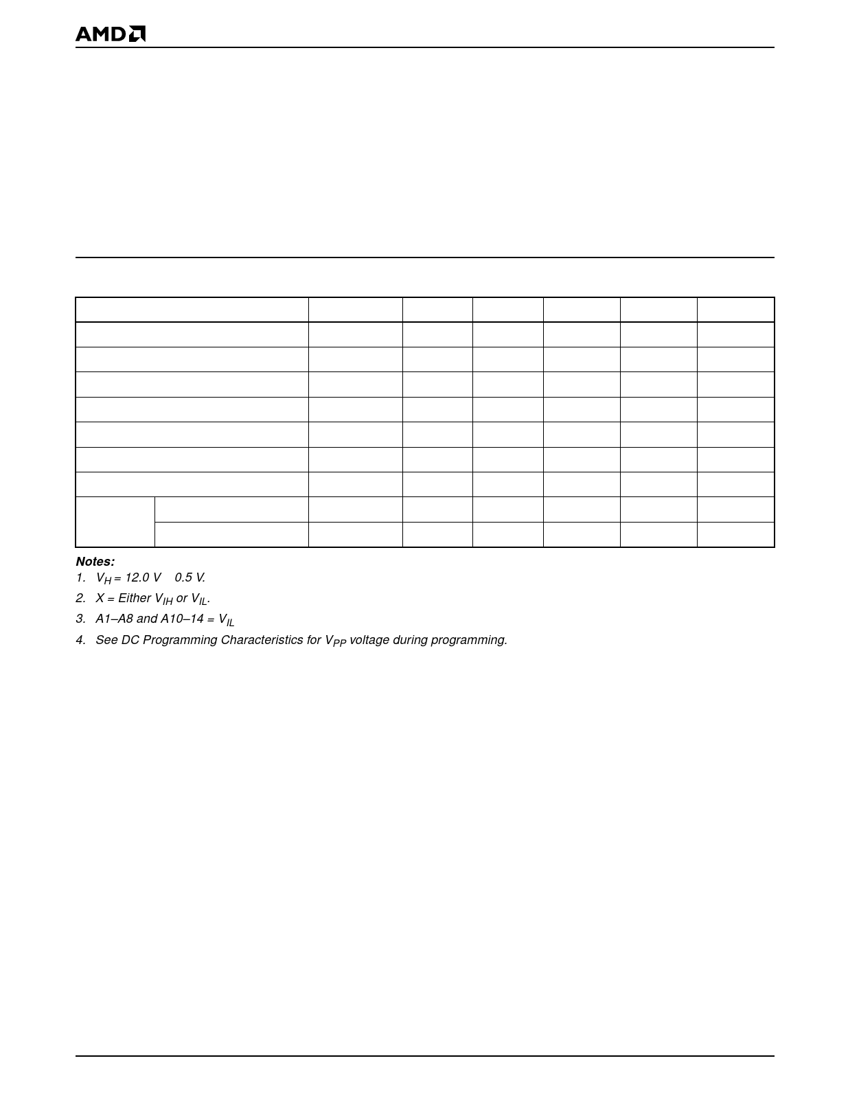
MODE SELECT TABLE
Mode
CE#
OE#
A0
A9
VPP
Outputs
Read
VIL
VIL
X
X
X
DOUT
Output Disable
X
VIH
X
X
X
High Z
Standby (TTL)
VIH
X
X
X
X
High Z
Standby (CMOS)
VCC ± 0.3 V
X
X
X
X
High Z
Program
VIL
X
X
X
VPP
DIN
Program Verify
VIL
VIL
X
X
VPP
DOUT
Program Inhibit
VIH
VIH
X
X
VPP
High Z
Autoselect
(Note 3)
Manufacturer Code
Device Code
VIL
VIL
VIL
VH
X
01h
VIL
VIL
VIH
VH
X
10h
Notes:
1. VH = 12.0 V ± 0.5 V.
2. X = Either VIH or VIL.
3. A1–A8 and A10–14 = VIL
4. See DC Programming Characteristics for VPP voltage during programming.
6
Am27C256
Share Link: 