AN8022L 查看數據表(PDF) - Panasonic Corporation
零件编号
产品描述 (功能)
生产厂家
AN8022L Datasheet PDF : 16 Pages
| |||
AN8022L, AN8022SB
Voltage Regulators
s Application Notes (continued)
[2] Operation descriptions (continued)
3. Over voltage protection circuit (OVP) (continued)
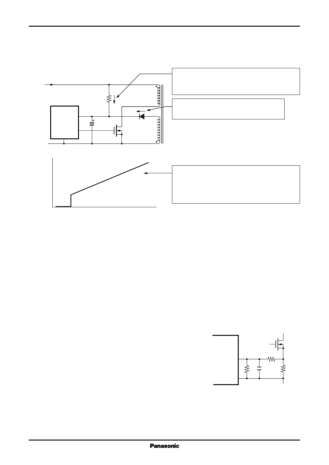
After AC rectification
Start resistor
R1
VCC
VOUT
GND
ICC
VCC− OVP
The current supply from the start resistor continues
as long as the voltage of the power supply input (AC)
is given.
After OVP starts operation, since the output is
stopped, this bias coil does not supply current.
* Select the resistance value so that the following
relationship can be kept by current supply from
the start resistor: VCC > VCC−OVP
At VCC-OVP (voltage under which OVP is released),
the operating current is temporarily increased.
This prevents VCC from exceeding its breakdown
voltage through the current from above mentioned.
VCC
Figure 4
4. Overcurrent protection circuit (OVP)
The overcurrent of the power supply output is proportional to the value of current flowing in the main switch
in the primary side (power MOSFET). Taking advantage of the above fact, by regulating the upper limit of the pulse
current flowing in the main switch, the circuit protects the parts which are easily damaged by the overcurrent.
For the current flowing in the main switch, the current detection is achieved by monitoring the voltage in both
ends of the low resistance, which is connected between the source of power MOSFET and the power supply GND.
When the power MOSFET is turned on and the threshold voltage of CLM (Current Limit) is detected, the
overcurrent protection circuit controls so that current can not flow further by turning off the output to turn off the
power MOSFET. The threshold voltage of CLM is approximately −200 mV (typical) under Ta = 25°C with respect
to GND of the IC. This control is repeated for each cycle. Once the overcurrent is detected, the off condition is
kept during that cycle, and it can not be turned on until the next cycle. The overcurrent detection method described
in the above is called pulse-by-pulse overcurrent detection. (Refer to figure 6.)
The R4, R5 and C3 in figure 5 construct the filter circuit, which
functions to remove the noise generated by the parasitic capaci-
tance which is equivalently formed at turning-on of the power
MOSFET.
GND R4
CLM
R5
C3
R3
• Notes on the detection level precision
Figure 5
This overcurrent detection level is reflected on the operating current level of the power supply overcurrent
protection. Therefore, if this detection level fluctuates with temperature or dispersion, the operating current level
of the power supply overcurrent protection also fluctuates. Since such level fluctuation increases the necessity of
withstand capability for the parts to be used and in the worst case it means the cause of destruction, the accuracy
of detection level is raised as much as possible for these ICs, the AN8022L and AN8022SB.
10
Share Link: 