AP3019 查看數據表(PDF) - BCD Semiconductor
零件编号
产品描述 (功能)
生产厂家
AP3019 Datasheet PDF : 15 Pages
| |||
Preliminary Datasheet
WHITE LED STEP-UP CONVERTER
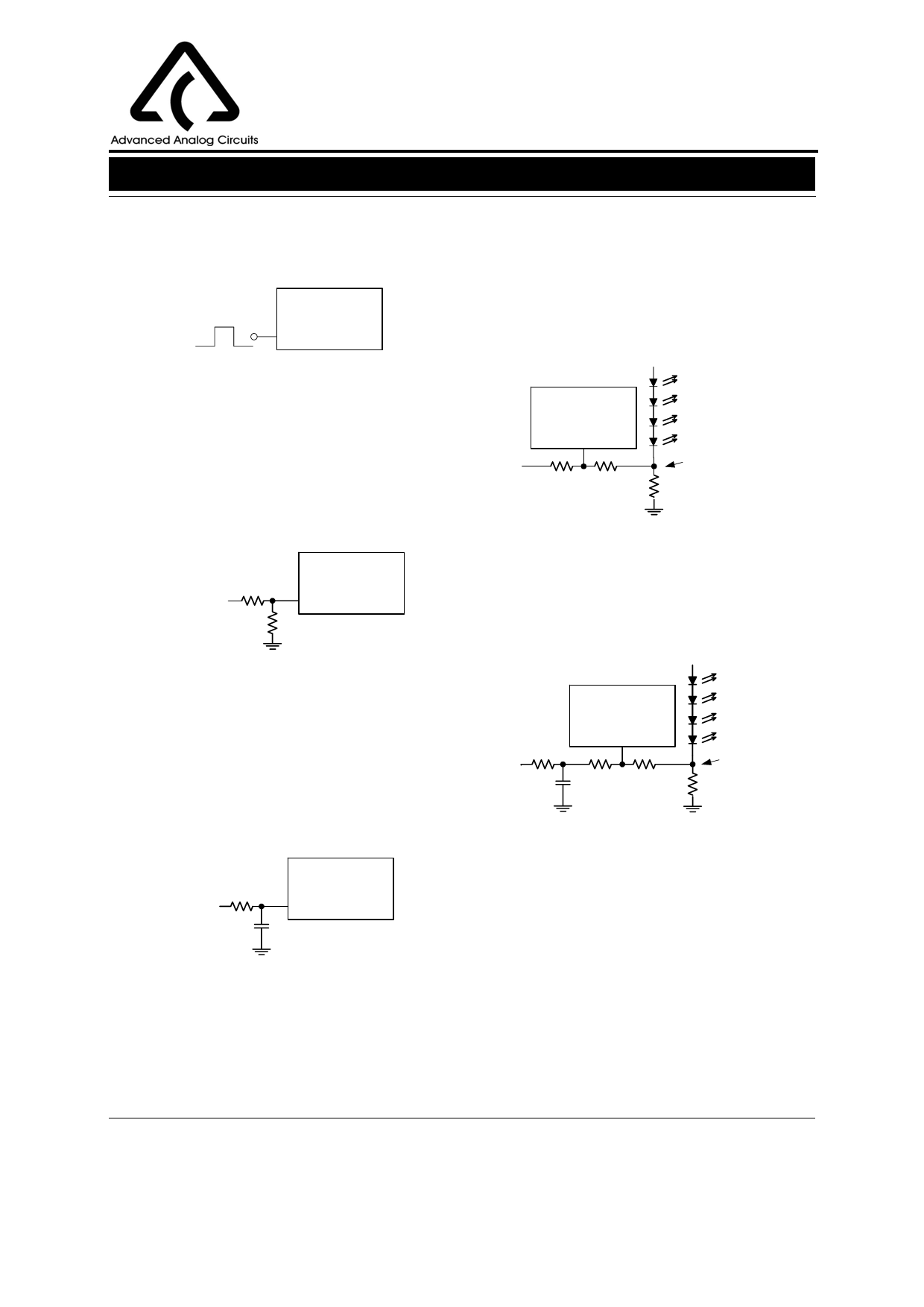
Application Information (Continued)
this PWM signal is 500Hz to 1KHz. Please refer to
Figure 21.
AP3019
CTRL
500Hz to 1KHz
AP3019
First, adding a constant DC voltage through a resistor
divider to FB pin can control the dimming. Changing
the DC voltage or resistor between the FB Pin and the
DC voltage can get appropriate luminous intensity.
Comparing with all kinds of PWM signal control, this
method features a stable output voltage and LEDs
current. Please refer Figure 24.
Figure 21. Dimming Control
Using a PWM Signal in CTRL Pin
Secondly, adding a constant DC voltage through a
resistor divider to CTRL pin can control the dimming.
The FB voltage is indirectly adjusted when the CTRL
pin voltage is between 50mV to 1.8V, which can be
used as dimming control. Please refer Figure 22.
R1
10K
VDC
0.1 to 3.6V R2
10K
AP3019
CTRL
AP3019
FB
VDC
R3
R2
90K
5K
Effective
Feedback Voltage
R1
10Ω
Figure 24. Dimming Control
Using DC Voltage
Second, using a filtered PWM signal can do it. The
filtered PWM signal can be considered as a varying
and adjustable DC voltage.
Figure 22. Dimming Control
Using a DC Voltage in CTRL Pin
Thirdly, using a filtered PWM signal adding to CTRL
pin can achieve dimming control. The filtered PWM
signal can be considered as an adjustable DC voltage.
It will change the FB voltage indirectly and achieve
dimming control. The circuit is shown in Figure 23.
AP3019
FB
PWM
R4
10K
C
0.1µF
R3
90K
R2
5K
Effective
Feedback Voltage
R1
10Ω
PWM
R
5K
C
100nF
AP3019
CTRL
Figure 23. Dimming Control
Using a Filtered PWM Signal Voltage in CTRL Pin
Figure 25. Dimming Control
Using a Filtered PWM Voltage
Third, using a logic signal to change the feedback
voltage. For example, the FB pin is connected to the
GND through a mosFET and a resistor. And this
mosFET is controlled a logic signal. The luminous
intensity of LEDs will be changed when the mosFET
turns on or off.
(2). Changing the Effective Feedback Voltage
There are three methods to change the effective
feedback voltage.
Apr. 2007 Rev. 1. 1
11
BCD Semiconductor Manufacturing Limited
Share Link: 