APU3137 查看數據表(PDF) - Advanced Power Electronics Corp
零件编号
产品描述 (功能)
生产厂家
APU3137 Datasheet PDF : 17 Pages
| |||
APU3137
THEORY OF OPERATION
Introduction
The APU3137 is a fixed frequency, voltage mode syn-
chronous controller and consists of a precision refer-
ence voltage, an error amplifier, an internal oscillator, a
PWM comparator, 1A peak gate driver, soft-start and
shutdown circuits (see Block Diagram).
The output voltage of the synchronous converter is set
and controlled by the output of the error amplifier; this is
the amplified error signal from the sensed output voltage
and the reference voltage.
This voltage is compared to a fixed frequency linear
sawtooth ramp and generates fixed frequency pulses of
variable duty-cycle, which drives the two N-channel ex-
ternal MOSFETs.The timing of the IC is provided through
an internal oscillator circuit which uses on-chip capaci-
tor to set the oscillation frequency to 200 KHz.
Soft-Start
The APU3137 has a programmable soft-start to control
the output voltage rise and limit the current surge at the
start-up. To ensure correct start-up, the soft-start se-
quence initiates when the Vc and Vcc rise above their
threshold (3.5V and 4.25V respectively) and generates
the Power On Reset (POR) signal. Soft-start function
operates by sourcing an internal current to charge an
external capacitor to about 3V. Initially, the soft-start func-
tion clamps the E/A’s output of the PWM converter and
disables the short circuit protection. During the power
up, the output starts at zero and voltage at Fb is below
0.4V. The feedback UVLO is disabled during this time
by injecting a current (64µA) into the Fb. This generates
a voltage about 1.6V (64µA×25K) across the negative
input of E/A and positive input of the feedback UVLO
comparator (see Fig3).
20uA
3V
SS/SD
64uA
Max
HDrv
POR
Comp
25K
Error Amp
LDrv
0.8V
25K
Fb
0.4V
64uA×25K=1.6V
When SS=0
POR
Feeback
UVLO Comp
Figure 3 - Soft-start circuit for APU3137.
The magnitude of this current is inversely proportional to
the voltage at soft-start pin.
The 20µA current source starts to charge up the exter-
nal capacitor. In the mean time, the soft-start voltage
ramps up, the current flowing into Fb pin starts to de-
crease linearly and so does the voltage at the positive
pin of feedback UVLO comparator and the voltage nega-
tive input of E/A.
When the soft-start capacitor is around 1V, the current
flowing into the Fb pin is approximately 32µA. The volt-
age at the positive input of the E/A is approximately:
32µA×25K = 0.8V
The E/A will start to operate and the output voltage starts
to increase. As the soft-start capacitor voltage contin-
ues to go up, the current flowing into the Fb pin will keep
decreasing. Because the voltage at pin of E/A is regu-
lated to reference voltage 0.8V, the voltage at the Fb is:
VFB = 0.8-25K×(Injected Current)
The feedback voltage increases linearly as the injecting
current goes down. The injecting current drops to zero
when soft-start voltage is around 2V and the output volt-
age goes into steady state.
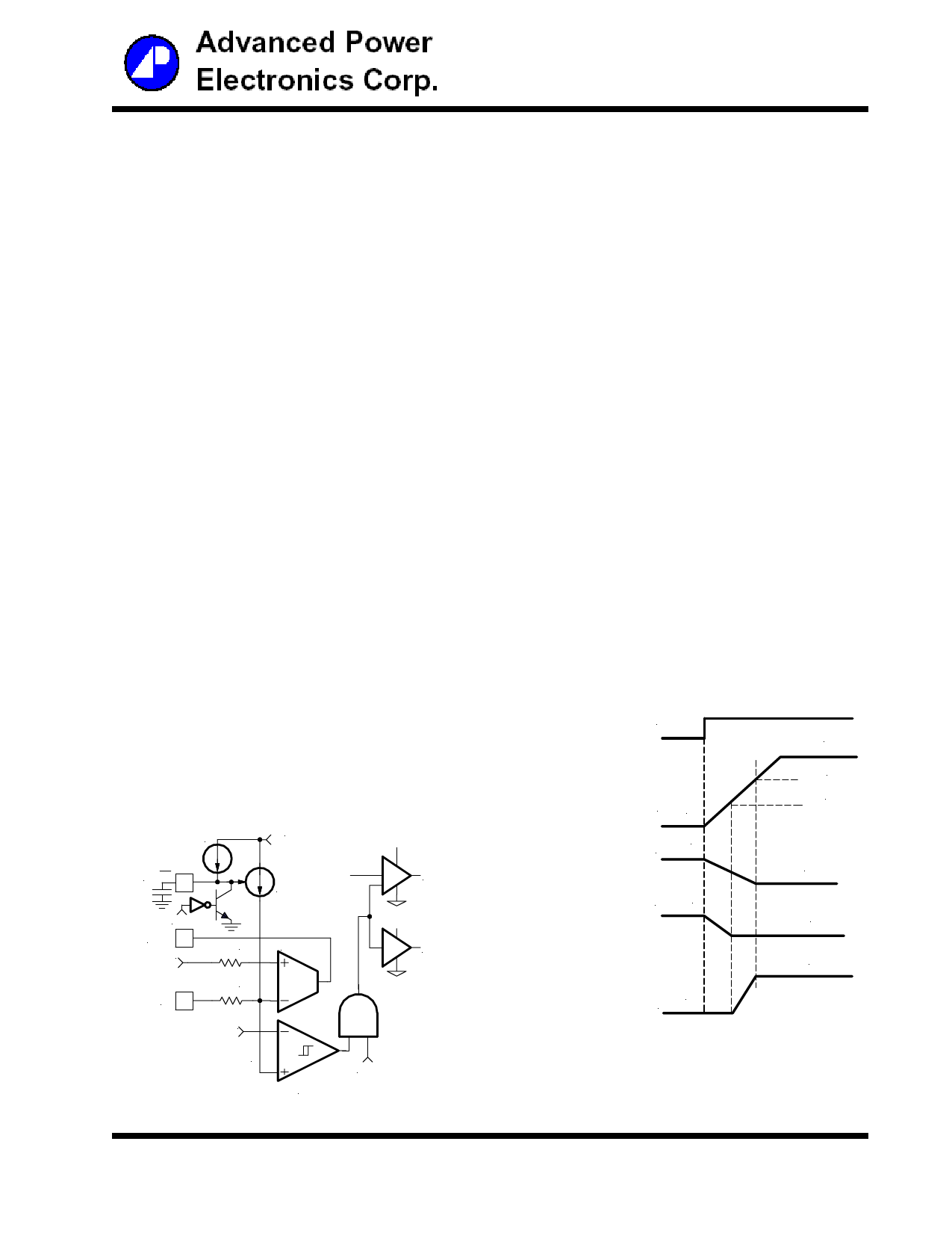
As shown in Figure 4, the positive pin of feedback UVLO
comparator is always higher than 0.4V, therefore, feed-
back UVLO is not functional during soft-start.
Output of UVLO
POR
3V
Soft-Start 0V
Voltage
64uA
Current flowing
into Fb pin
Voltage at negative input ≅1.6V
of Error Amp and Feedback
UVLO comparator
≅2V
≅1V
0uA
0.8V
0.8V
0V
Voltage at Fb pin
Figure 4 - Theoretical operational waveforms
during soft-start.
5/17
Share Link: 