APW717818QBI-TRG 查看數據表(PDF) - Anpec Electronics
零件编号
产品描述 (功能)
生产厂家
APW717818QBI-TRG Datasheet PDF : 16 Pages
| |||
APW7178
Pin Description
PIN
NO.
NAME
FUNCTION
Pulse Frequency Mode Select. Pulling this pin to logic high forces Buck converter to enter PWM mode.
1
PS
Pulling it low places the IC into automatic mode which depends on the output load current to operate in
either PFM(Pulse Frequency Modulation) or PWM mode automatic switching.
Enable Control Input. Forcing this pin above 1.0V enables the device. Forcing this pin below 0.4V shuts it
2
RUN down. In shutdown, all functions are disabled to decrease the supply current below 0.5µA. Do not leave
RUN pin floating.
3
VIN
Device and Converter Supply Pin. Must be closely decoupled to GND with a 4.7µF or greater ceramic
capacitor.
4
SW
Switch Node Connected to Inductor. This pin connects to the drains of the internal main and synchronous
power MOSFETs switches.
5
GND Power and Signal Ground.
In the adjustable version, feedback function is available. The feedback voltage is decided by an external
6
FB/VOUT resistive divider across the output. In the fixed version, an internal resistive divider divides the output
voltage down for comparison to the internal reference voltage.
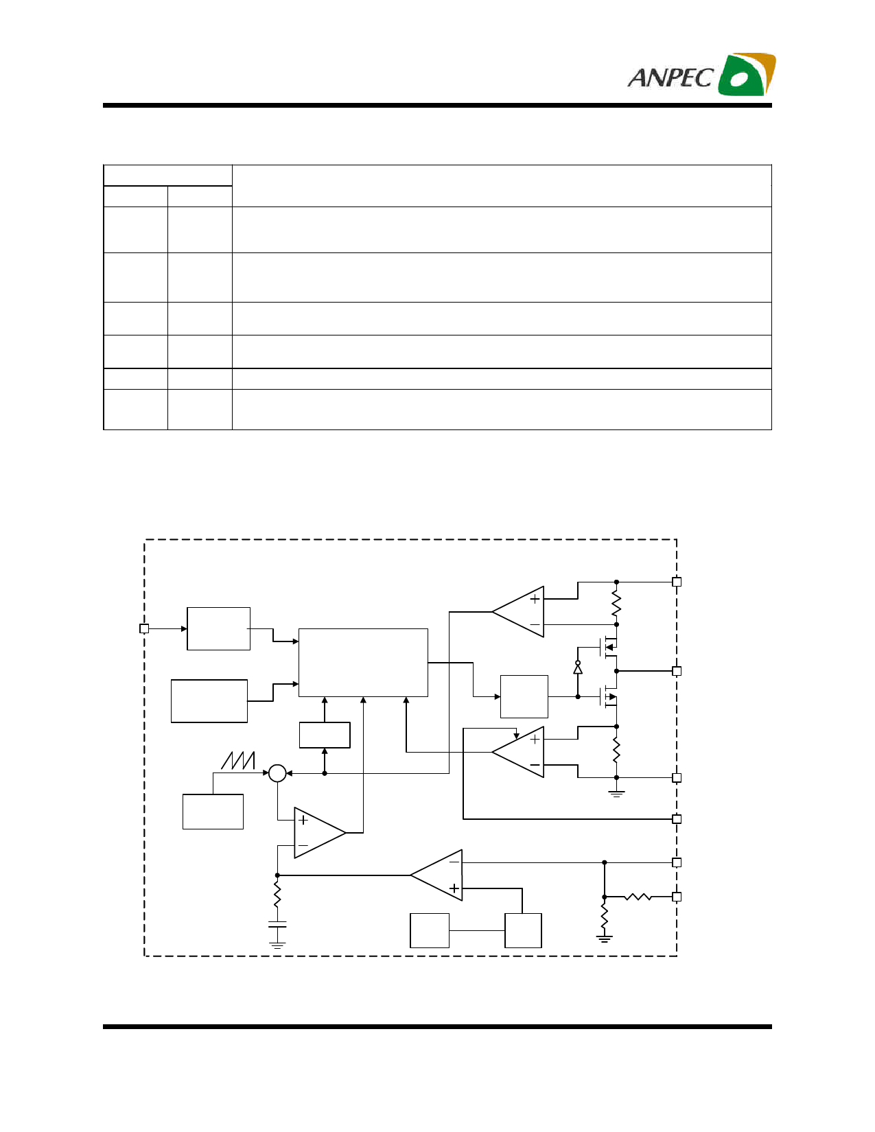
Block Diagram
RUN
Shutdown
Control
Over-
Temperature
Protection
Slope
Compensation
Oscillator
Current
Sense
Amplifier
Logic Control
Current
-Limit
∑
Gate
Driver
Zero-
Crossing
Comparator
ICMP
COMP
Error
Amplifier
EAMP
Soft-
Start
VREF
0.6V
VIN
SW
GND
PS
FB
(APW7178)
VOUT
(APW7178-XX)
Copyright © ANPEC Electronics Corp.
7
Rev. A.2 - Jan., 2011
www.anpec.com.tw
Share Link: 