AS1301A-BWLT 查看數據表(PDF) - austriamicrosystems AG
零件编号
产品描述 (功能)
生产厂家
AS1301A-BWLT Datasheet PDF : 16 Pages
| |||
AS1301
Data Sheet - Detailed Description
Switch Configuration
The AS1301 has nine built-in power switches in the shape of two coupled H-bridge topologies. The system features
1:2 and 2:3 operation mode as well as an 1:1 operation where the input is directly connected to the output. This
feedthrough mode is suitable for input voltages higher than the output voltage.
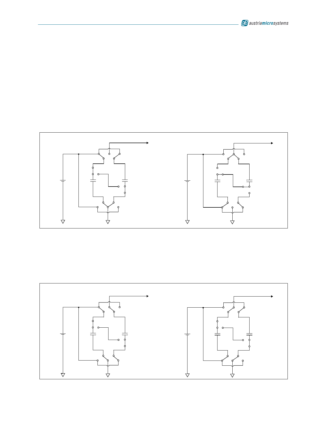
In 2:3 operation mode two flying capacitors are placed in series and each capacitor is charged to a half of the input
voltage. In pumping phase the flying capacitors are place in parallel. The bottom-plate of the parallel flying capacitors
CFLY1 and CFLY2 is then connected to the input voltage so that the voltage at the top-plate of the flying capacitors is
boosted to a voltage equal to VBATT+ VBATT/2. By connecting the top-plate of the capacitors to the output, the output
voltage in 2:3 mode can be up to one and a half of VBATT. If the top-plate voltage is higher than 5V, the regulation loop
adapts the power transistor’s on-resistance to drop some voltage. The 2:3 operation mode runs in single-phase
operation only.
Figure 27. 2:3 Single Phase Operating Mode
Charging Flying Capacitors
VOUT
Generating Output Voltage
VOUT
VBATT
SW2
CFLY1
SW1
CFLY2
SW3
SW4
VBATT
SW2
CFLY1
SW1
CFLY2
SW3
SW4
In 1:2 operation mode just one of both flying capacitors is placed in series to the input voltage, and therefore charged
to the input voltage. During pumping phase the input voltage is connected to the bottom of the charged flying capacitor
CFLY. The voltage at the top-plate of the capacitor is now boosted to 2VBATT. By connecting the top-plate of the
capacitor to the output, the output can be charged to double of VBATT. If the top-plate voltage is higher than 5V the
regulation loop limits the charge transfer to the output. In collaboration with the second flying capacitor this mode
features dual-phase operation.
Figure 28. 1:2 Dual Phase Operating Mode
Charging CFLY1, CFLY2 used for output voltage
VOUT
Charging CFLY2, CFLY1 used for output voltage
VOUT
VBATT
SW2
CFLY1
SW1
CFLY2
SW3
SW4
VBATT
SW2
CFLY1
SW1
CFLY2
SW3
SW4
www.austriamicrosystems.com
Revision 1.00
10 - 16
Share Link: 