AS1108 查看數據表(PDF) - austriamicrosystems AG
零件编号
产品描述 (功能)
生产厂家
AS1108 Datasheet PDF : 19 Pages
| |||
AS1108
Data Sheet
austriamicrosystems
4x8 LED Dot Matrix Driver
4x8 LED Dot Matrix Driver
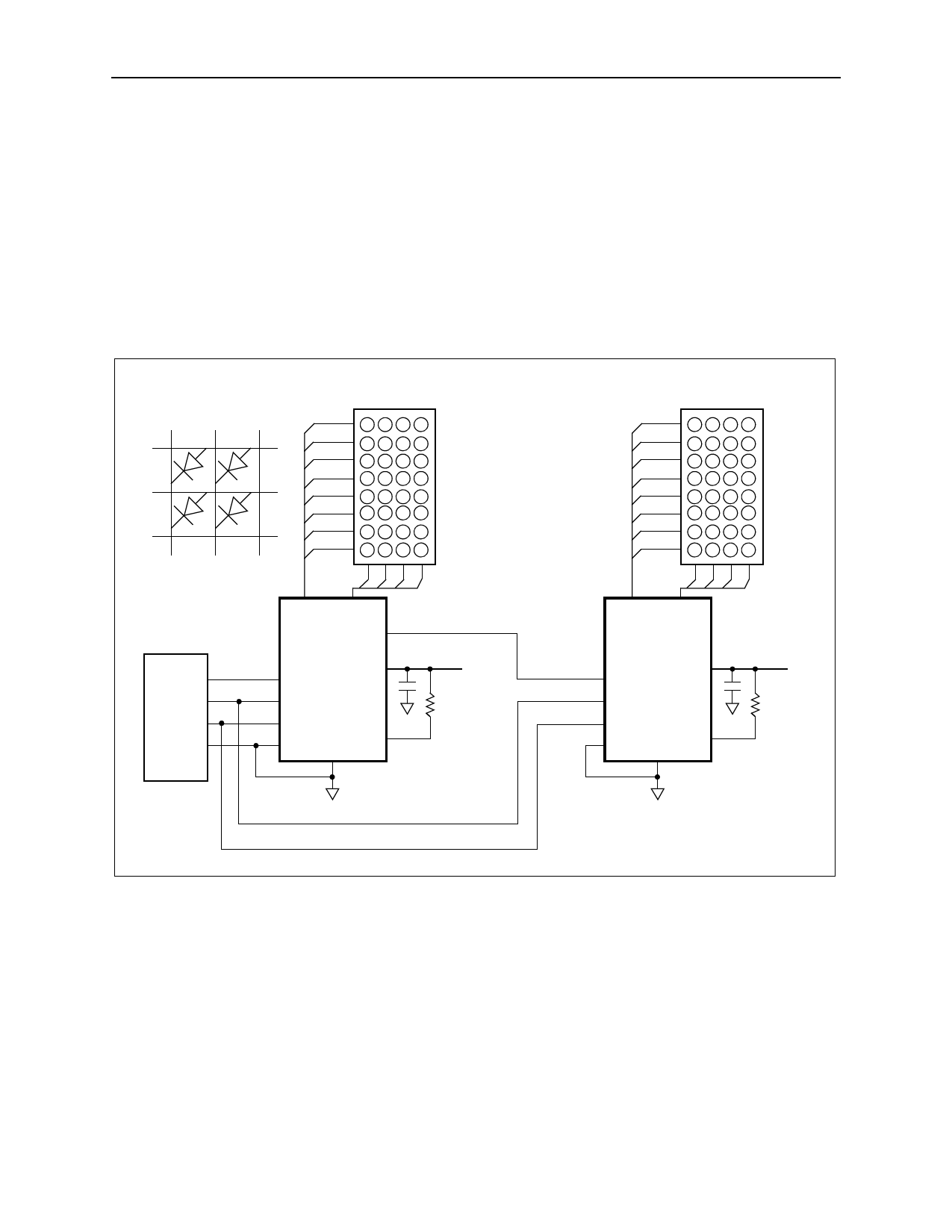
The application example in Figure 11 shows the AS1108 as a 4x8 LED dot matrix driver.
The LED columns have common cathodes and are connected to the DIG0:3 outputs. The rows are connected to the
segment drivers. Each of the 32 LEDs can be addressed separately. The columns are selected via the digits as listed
in Table 6 on page 7.
The Decode Enable Register (see page 8) must be set to ‘00000000’ as described in Table 8 on page 8. Single LEDs
in a column can be addressed as described in Table 11 on page 9, where bit D0 corresponds to segment G and bit D7
corresponds to segment DP.
Note: For a multiple-digit dot matrix, multiple AS1108 devices must be cascaded.
Figure 11. Application Example as LED Dot Matrix Driver
Diode Arrangement
SEG G
SEG F
SEG E
SEG D
SEG C
SEG B
SEG A
SEG DP
4x8 LED
Dot Matrix
SEG G
SEG F
SEG E
SEG D
SEG C
SEG B
SEG A
SEG DP
4x8 LED
Dot Matrix
Micro-
Processor
SEG A:G DIG0:3
SEG DP
DOUT
AS1108
DIN
VDD
LOAD/CSN
CLK
GND
ISET
GND
VBAT
9.53kΩ
SEG A:G DIG0:3
SEG DP
AS1108
DIN
VDD
LOAD/CSN
CLK
GND
ISET
GND
VBAT
9.53kΩ
Cascading Drivers
If more than 4 digits or 32 LEDs are needed, it is recommended to use the AS1106/AS1107, although several AS1108
devices can be cascaded.
The example in Figure 4 drives 2 dot matrix digits using a 4-wire microprocessor interface. All Scan-Limit Registers
should be set to the same value so that one display will not appear brighter than the other.
For example, to display 6 digits, set both Scan-Limit Registers to display 3 digits so that both displays have a 1/3 duty
cycle per digit. If 5 digits are needed, set both Scan-Limit Registers to display 3 digits and leave one digit unconnected.
Otherwise, if one driver is set to display 3 digits and the other to display 2 digits one display will appear brighter
because its duty cycle per digit will be 1/2 and the other display’s duty cycle will be 1/3.
Note: Refer to No-Op Register (0xX0) on page 11 for additional information.
www.austriamicrosystems.com
Revision 2.1
14 - 19
Share Link: 