AS1341-BTDT-6K 查看數據表(PDF) - austriamicrosystems AG
零件编号
产品描述 (功能)
生产厂家
AS1341-BTDT-6K Datasheet PDF : 18 Pages
| |||
AS1341
Datasheet - Application Information
9.3 Setting Current Limit
The AS1341 adjustable peak current limit is set by connecting ILIMIT as shown in Table 4.
Table 4. Setting Peak Current Limit
Current Limit
700mA
1400mA
ILIMIT Connected To
GND
IN
The current limit chosen should reflect the maximum load current. The maximum output current is half of the peak current limit. Choosing a lower
current limit allows using an inductor with a lower current rating, however, it requires a higher inductance (see Inductor Selection) and does not
allow for reduced inductor package size.
9.4 Inductor Selection
The AS1341 operates with a wide range of inductance values. For most applications, values between 10µH and 47µH work best with the
controller’s high switching frequency. Larger inductor values will reduce the switching frequency and thereby improve efficiency and EMI.
Note: The four key factors in inductor selection are inductance value, saturation rating, series resistance, and size.
The trade-off for improved efficiency is a higher output ripple and slower transient response. On the other hand, low-value inductors respond
faster to transients, improve output ripple, offer smaller physical size, and minimize cost. If the inductor value is too small, the peak inductor
current exceeds the current limit due to current-sense comparator propagation delay, potentially exceeding the inductor’s current rating.
Calculate the minimum inductance value as follows:
LMIN = ((VINMAX - VOUTPUT) x tONMIN/ILXPEAK
(EQ 3)
Where:
tONMIN = 1µs
The inductor saturation current rating must be greater than the peak switch current limit, plus the overshoot due to the 250ns current-sense
comparator propagation delay. Saturation occurs when the magnetic flux density of the inductor reaches the maximum level the core can support
and the inductance starts to fall. Choose an inductor with a saturation rating greater than IPEAK in the following equation:
IPEAK = (ILXPEAK + (VIN - VOUTPUT) x 250ns)/L
(EQ 4)
Inductor series resistance affects both efficiency and dropout voltage (see Dropout Voltage on page 9). High series resistance limits the
maximum current available at lower input voltages, and increases the dropout voltage. For optimum performance, select an inductor with the
lowest possible DC resistance that fits in the allotted dimensions.
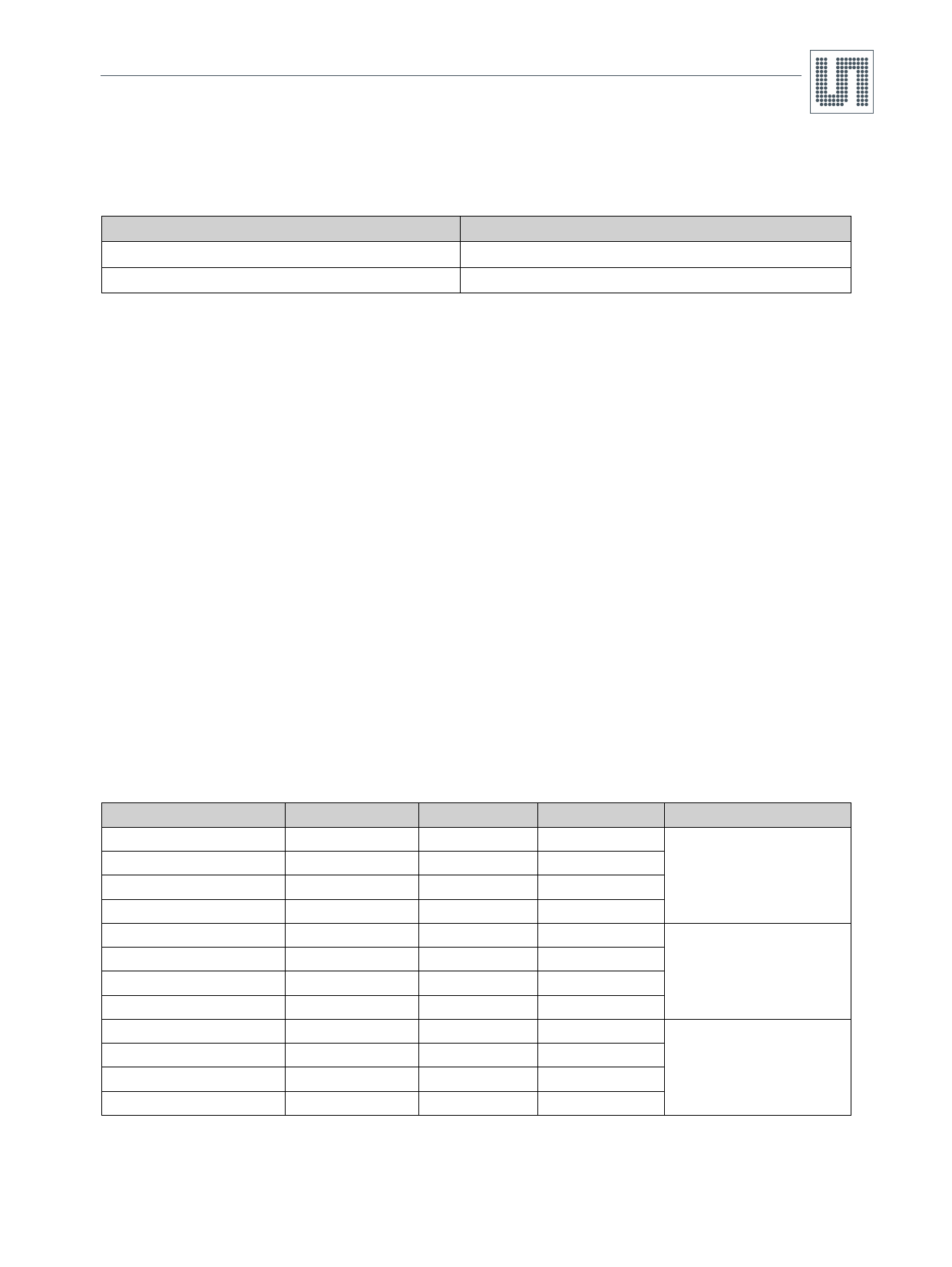
Table 5. Recommended Inductors
Part Number
MSS6132-103ML
LPS4018-472ML
MSS6132-393ML
LPS4018-223ML
CDRH6D28NP-150
CDRH5D18NP-4R1
CDRH6D28NP-470
CDRH5D18NP-220
LQH66SN-100M03
LQH55DN-150M03
LQH66SN-470M03
LQH55DN-470M03
L
10µH
4.7µH
39µH
22µH
15µH
4.1µH
47µH
22µH
10µH
15µH
47µH
47µH
DCR
85mΩ
125mΩ
345mΩ
360mΩ
62mΩ
57mΩ
176mΩ
215mΩ
36mΩ
150mΩ
170mΩ
400mΩ
Current Rating
1.4A
1.8A
0.8A
0.7A
1.4A
1.95A
0.8A
0.8A
1.6A
1.4A
0.8A
0.8A
Manufacturer
Coilcraft
www.coilcraft.com
Sumida
www.sumida.com
Murata
www.murata.com
www.ams.com/DC-DC_Step-Up/AS1341
Revision 1.09
11 - 18
Share Link: 