AT49BV160D 查看數據表(PDF) - Atmel Corporation
零件编号
产品描述 (功能)
生产厂家
AT49BV160D Datasheet PDF : 29 Pages
| |||
AT49BV160D(T)
4.7 Read Status Register
The status register indicates the status of device operations and the success/failure of that oper-
ation. The Read Status Register command causes subsequent reads to output data from the
status register until another command is issued. To return to reading from the memory, issue a
Read command.
The status register bits are output on I/O7 - I/O0. The upper byte, I/O15 - I/O8, outputs 00H
when a Read Status Register command is issued.
The contents of the status register [SR7:SR0] are latched on the falling edge of OE or CE
(whichever occurs last), which prevents possible bus errors that might occur if status register
contents change while being read. CE or OE must be toggled with each subsequent status read,
or the status register will not indicate completion of a Program or Erase operation.
When the Write State Machine (WSM) is active, SR7 will indicate the status of the WSM; the
remaining bits in the status register indicate whether the WSM was successful in performing the
preferred operation (see Table 4-1).
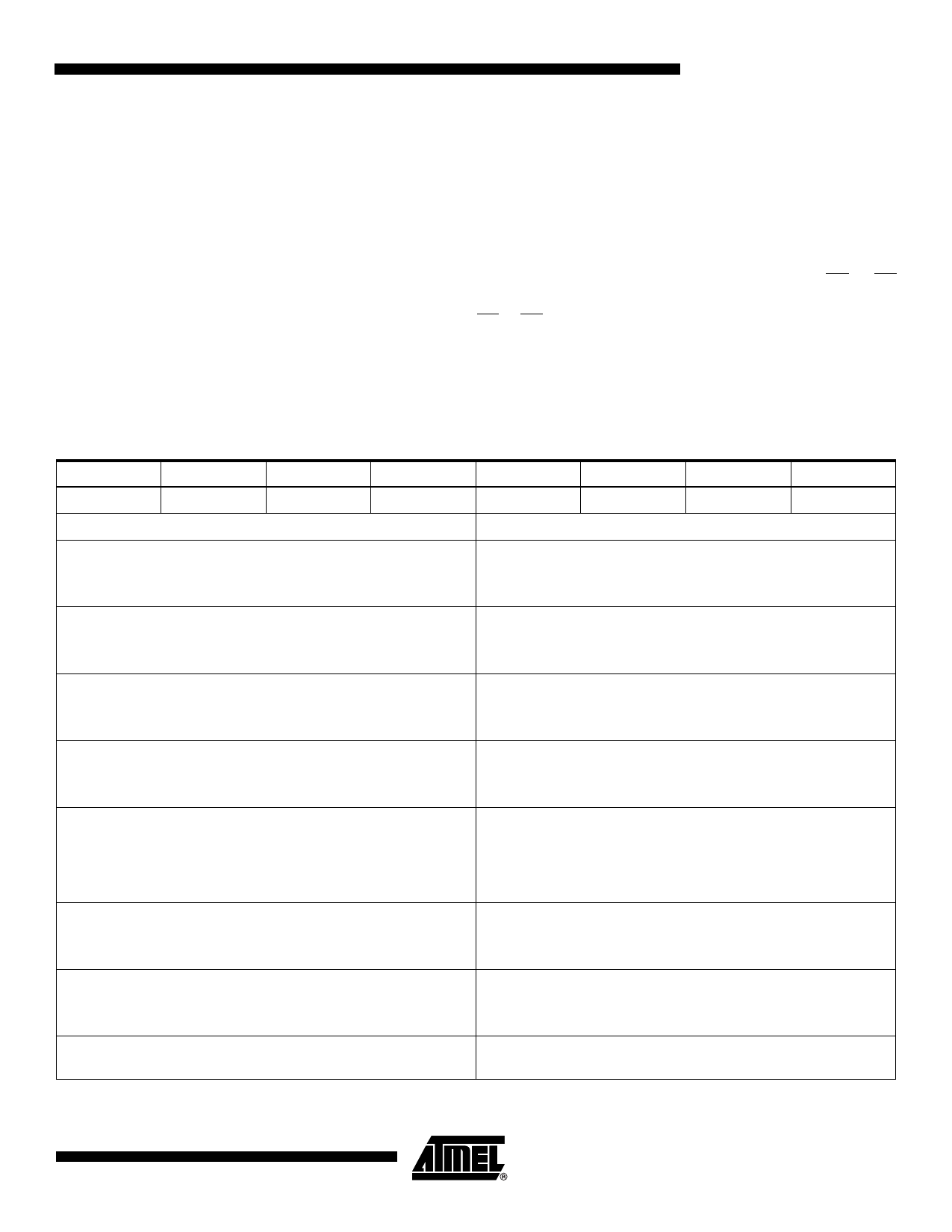
Table 4-1. Status Register Bit Definition
WSMS
ESS
ES
PS
VPPS
PSS
SLS
R
7
6
5
4
3
2
1
0
Notes
SR7 WRITE STATE MACHINE STATUS (WSMS)
1 = Ready
0 = Busy
Check Write State Machine bit first to determine Word Program
or Sector Erase completion, before checking program or erase
status bits.
SR6 = ERASE SUSPEND STATUS (ESS)
1 = Erase Suspended
0 = Erase In Progress/Completed
When Erase Suspend is issued, WSM halts execution and sets
both WSMS and ESS bits to “1” – ESS bit remains set to “1” until
an Erase Resume command is issued.
SR5 = ERASE STATUS (ES)
1 = Error in Sector Erase
0 = Successful Sector Erase
When this bit is set to “1”, WSM has applied the max number of
erase pulses to the sector and is still unable to verify successful
sector erasure.
SR4 = PROGRAM STATUS (PS)
1 = Error in Programming
0 = Successful Programming
When this bit is set to “1”, WSM has attempted but failed to
program a word
SR3 = VPP STATUS (VPPS)
1 = VPP Low Detect, Operation Abort
0 = VPP OK
The VPP status bit does not provide continuous indication of VPP
level. The WSM interrogates VPP level only after the Program or
Erase command sequences have been entered and informs the
system if VPP has not been switched on. The VPP is also checked
before the operation is verified by the WSM.
SR2 = PROGRAM SUSPEND STATUS (PSS)
1 = Program Suspended
0 = Program in Progress/Completed
When Program Suspend is issued, WSM halts execution and
sets both WSMS and PSS bits to “1”. PSS bit remains set to “1”
until a Program Resume command is issued.
SR1 = SECTOR LOCK STATUS (SLS)
1 = Prog/Erase attempted on a locked sector; Operation aborted.
0 = No operation to locked sectors
If a Program or Erase operation is attempted to one of the locked
sectors, this bit is set by the WSM. The operation specified is
aborted and the device is returned to read status mode.
SR0 = RESERVED FOR FUTURE ENHANCEMENTS (R)
This bit is reserved for future use and should be masked out
when polling the status register.
Note: 1. A Command Sequence Error is indicated when SR1, SR3, SR4 and SR5 are set.
5
3591C–FLASH–6/06
Share Link: 