ATM3224C-NC-FTH 查看數據表(PDF) - AZ Displays
零件编号
产品描述 (功能)
生产厂家
ATM3224C-NC-FTH Datasheet PDF : 15 Pages
| |||
ATM3224C-NC-FTH 5" TFT
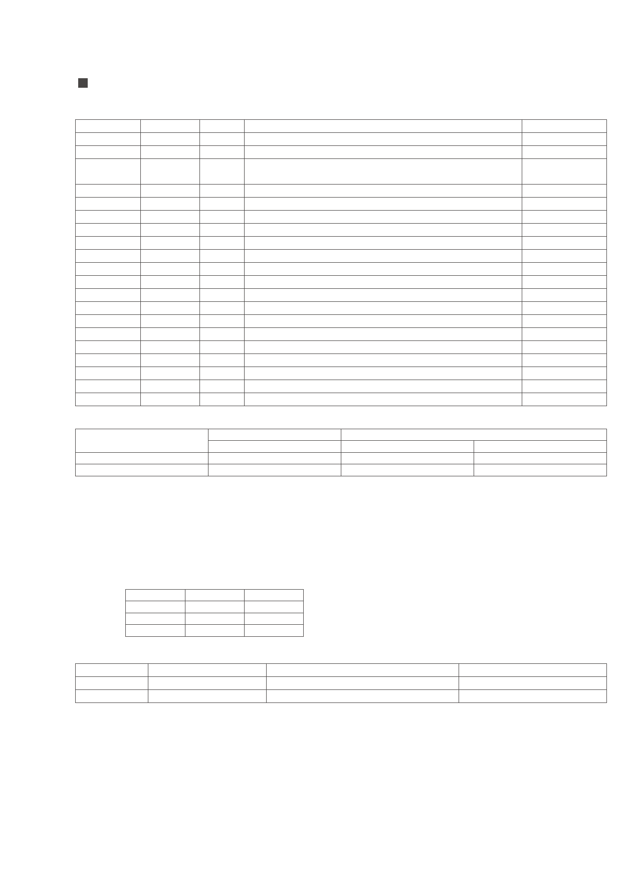
INPUT / OUTPUT TERMINALS
TFT LCD Panel Driving
Pin No
Symbol I/O
1
/HSY
I/O
2
FRP
O
3
CSY /
I
HSY
4
VGH
I
5
VGL
I
6
VB
I
7
VR
I
8
VG
I
9
GND
I
10
VDD
I
11
VCC
I
12
GND
I
13
CKC
I
14
/VSY
I/O
15
PSI
O
16
PSC
O
17
NC
I
18
UD
I
19
RL
I
20
NP
I/O
Description
Horizontal sync input / output
Video polarity alternating signal
Composite sync signal
Supply voltage for gate driver (Hi level)
Supply voltage for gate driver (Low level)
Video signal (Blue)
Video signal (Red)
Video signal (Green)
Ground
Supply voltage for controller
Supply voltage for source driver
Ground
Control pin for select I/O signal
Vertical sync input/output
Synchronize pulse for decoder
Synchronize pulse for DC-DC converter
No connection / Vertical sync signal
Up / Down control
Right / Left shift control
NTSC / PAL selection signal (Low : PAL, High : NTSC)
Remark
Note 1
Note 2
Note 3
Note 4
Note 5
Note 1
Note 1
Note 7
Note 6
Note 8
Note 1: This module can support 2 input mode. Pin #13 of CKC is for the 2 input mode selection.
Parameter
Select pin (CKC)
CKC (pin #13)
Description
CSY / HSY (pin #3)
NC / VSY (pin #17)
Composite sync mode
High
CSY (positive edge)
-
Sync separate mode
Low
HSY (negative edge)
VSY (positive edge)
The default mode of this module is composite sync mode (CKC = high)
If you use sync separate mode (CKC = low), please contact AZ Displays to modify some components of PCBA.
Note 2: VGH (typ) = +17V
Note 3: VGL (typ) = -15V
Note 4: VDD (typ) = +5V
Note 5: VCC (typ) = +5V
Note 6: Low (0V) for shift Right; input Hi (+5.0V) for inverse (shift Left).
Note 7: Hi (+5.0V) for Down; Low (0V) for Up.
Note 8: PAL = Low (0V), NTSC = Hi (+5.0V)
(If use auto detect, this pin is output, otherwise this pin is input)
Low
High
Note 6
Right
Left
Note 7
Down
Up
Note 8
PAL
NTSC
Backlight driving
Pin No
Symbol
Description
1
VL1
Input terminal (Hi voltage side)
3
VL2
Input terminal (Low voltage side)
Note 9: Low voltage side of backlight inverter connects with Ground of inverter circuits.
Remark
Wire color : pink
Wire color : white (Note 9)
Input / Output connector
LCD module: Molex 52271-2090
FFC down connector; 20 pins, pitch: 1.0mm
Backlight connector: JST BHR-03VS-1
3 pins, pitch: 4.0mm, Pink: high voltage, White: low voltage
Page 3 of 15
Share Link: 