TC815CBU 查看數據表(PDF) - Microchip Technology
零件编号
产品描述 (功能)
生产厂家
TC815CBU
Microchip Technology

TC815CBU Datasheet PDF : 26 Pages
| |||
3.0 DETAILED DESCRIPTION
3.1 Resistance, Voltage, Current
Measurement Selection
The TC815 is designed to measure voltage, current,
and resistance. Auto-ranging is available for resistance
and voltage measurements. The OHMS (Pin 2) and
I (Pin 63) input controls are normally pulled internally to
VCC. By tying these pins to Digital Ground (Pin 58), the
TC815 is configured internally to measure resistance,
voltage, or current. The required signal combinations
are shown in Table 3-1.
TABLE 3-1: MEASUREMENT SELECTION
LOGIC
Function Select Pin
Selected
OHM (Pin 2)
I (Pin 63) Measurement
0
0
Voltage
0
1
Resistance
1
0
Current
1
1
Voltage
Note 1: 0 = Digital Ground
2: 1 = Floating or Tied to VCC
3: OHM and I are normally pulled internally high to
VCC (Pin 28). This is considered a logic “1.”
4: Logic “0” is the potential at digital ground (Pin 58).
3.2 Resistance Measurements
(Ohms and Low Power Ohms)
The TC815 can be configured to reliably measure in-
circuit resistances shunted by semiconductor junc-
tions. The TC815 Low Power Ohms Measurement
mode limits the probe open circuit voltage. This pre-
vents semiconductor junctions in the measured system
from turning on.
In the Resistance Measurement mode, the Ω/LOWΩ
(Pin 62) input selects the Low Power Ohms Measure-
ment mode. For low power ohms measurements,
Ω/LOWΩ (Pin 62) is momentarily brought low to digital
ground potential. The TC815 sets up for a low power
ohms measurement with a maximum open circuit
probe voltage of 0.35V above analog common. In the
Low Power Ohms mode, an LCD display annunciator,
LOWΩ, will be activated. On power-up, the Low Power
Ohms mode is not active.
If the Manual mode has been selected, toggling
Ω/LOWΩ will reset the TC815 back to the Auto-Range
mode. In Manual mode, the decision to make a normal
or low power ohms measurement should be made
before selecting the desired range.
TC815
The low power ohms measurement is not available on
the 100Ω full scale range. Open circuit voltage on this
range is below 2.8V. The standard resistance values
are listed in Table 3-2.
R8, a positive temperature coefficient resistor, and the
6.2V zener Z1 in Figure 3-1, provide input voltage pro-
tection during ohms measurements.
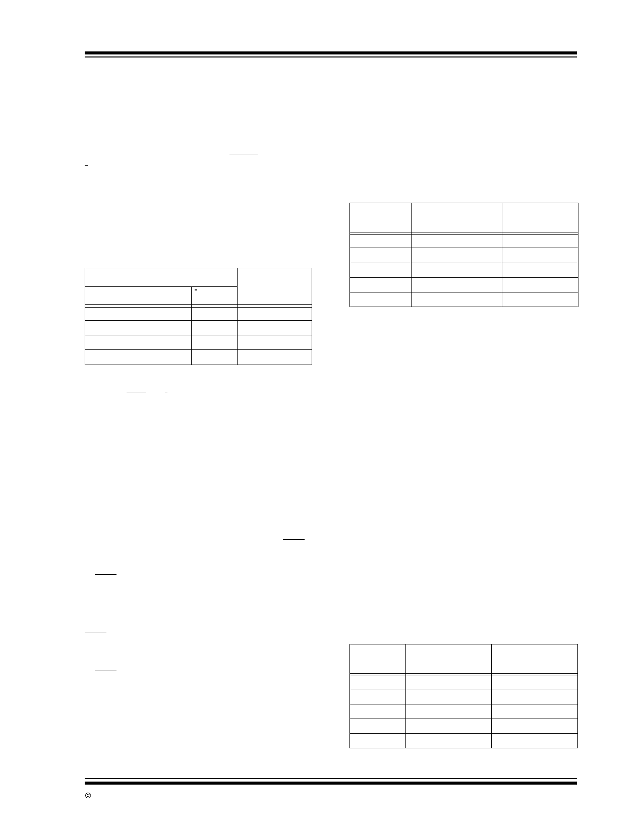
TABLE 3-2: OHMS RANGE LADDER
NETWORK
Full Scale
Range
200Ω
2000Ω
20kΩ
200kΩ
2,000kΩ
Standard
Resistance
163.85 Ω (R1)
1638.5 kΩ (R2)
16,385Ω (R3)
16385Ω (R4)
1,638,500Ω (R5)
Low Power
Ohms Mode
NO
YES
YES
YES
YES
3.3 Ratiometric Resistance
Measurements
The TC815 measures resistance ratiometrically. Accu-
racy is set by the external standard resistors connected
to Pin 35 through 39. A Low Power Ohms mode may
be selected on all but the 200Ω full scale range. The
Low Power Ohms mode limits the voltage applied to the
measured system. This allows accurate “in-circuit”
measurements when a resistor is shunted by semicon-
ductor junctions. Full auto-ranging is provided. External
precision standard resistors are automatically switched
to provide the proper range.
Figure 3-1 shows a detailed block diagram of the
TC815 configured for ratiometric resistance measure-
ments. During the signal integrate phase, the reference
capacitor charges to a voltage inversely proportional to
the measured resistance, RX. Figure 3-2 shows the
conversion accuracy relies on the accuracy of the
external standard resistors only.
Normally the required accuracy of the standard resis-
tances will be dictated by the accuracy specifications of
the users end product. Table 3-3 gives the equivalent
ohms per count for various full scale ranges to allow
users to judge the required resistor for accuracy.
TABLE 3-3: REFERENCE RESISTORS
Full Scale
Range
200k
2k
20k
200k
2M
Reference
Resistor
163.85
1638.5
16385
163850
1638500
Ω/Count
0.1
1
10
100
1000
© 2002 Microchip Technology Inc.
DS21474B-page 7
Share Link: