LM7818CK 查看數據表(PDF) - International Cmos Technology
零件编号
产品描述 (功能)
生产厂家
LM7818CK Datasheet PDF : 18 Pages
| |||
Application Hints (Continued)
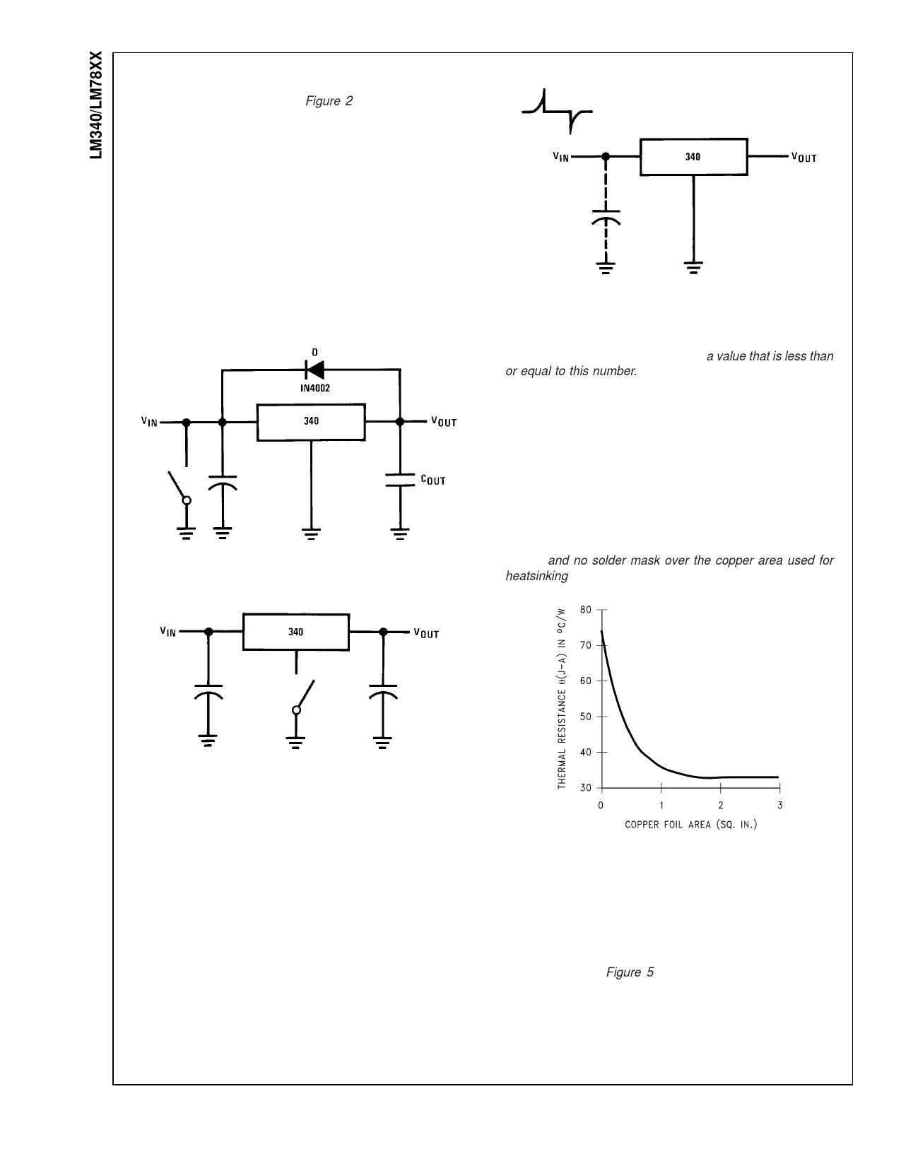
Regulator Floating Ground (Figure 2): When the ground
pin alone becomes disconnected, the output approaches the
unregulated input, causing possible damage to other circuits
connected to VOUT. If ground is reconnected with power
“ON”, damage may also occur to the regulator. This fault is
most likely to occur when plugging in regulators or modules
with on card regulators into powered up sockets. Power
should be turned off first, thermal limit ceases operating, or
ground should be connected first if power must be left on.
Transient Voltages: If transients exceed the maximum
rated input voltage of the device, or reach more than 0.8V
below ground and have sufficient energy, they will damage
the regulator. The solution is to use a large input capacitor, a
series input breakdown diode, a choke, a transient suppres-
sor or a combination of these.
FIGURE 1. Input Short
00778108
00778110
FIGURE 3. Transients
When a value for θ(H–A) is found using the equation shown,
a heatsink must be selected that has a value that is less than
or equal to this number.
θ(H–A) is specified numerically by the heatsink manufacturer
in this catalog, or shown in a curve that plots temperature
rise vs power dissipation for the heatsink.
HEATSINKING TO-263 AND SOT-223 PACKAGE PARTS
Both the TO-263 (“S”) and SOT-223 (“MP”) packages use a
copper plane on the PCB and the PCB itself as a heatsink.
To optimize the heat sinking ability of the plane and PCB,
solder the tab of the plane.
shows for the TO-263 the measured values of θ(J–A) for
different copper area sizes using a typical PCB with 1 ounce
copper and no solder mask over the copper area used for
heatsinking.
00778109
FIGURE 2. Regulator Floating Ground
00778139
FIGURE 4. θ(J–A) vs Copper (1 ounce)
Area for the TO-263 Package
As shown in the figure, increasing the copper area beyond 1
square inch produces very little improvement. It should also
be observed that the minimum value of θ(J–A) for the TO-263
package mounted to a PCB is 32˚C/W.
As a design aid, Figure 5 shows the maximum allowable
power dissipation compared to ambient temperature for the
TO-263 device (assuming θ(J–A) is 35˚C/W and the maxi-
mum junction temperature is 125˚C).
www.national.com
10
Share Link: 