BD9011EKN 查看數據表(PDF) - ROHM Semiconductor
零件编号
产品描述 (功能)
生产厂家
BD9011EKN
ROHM Semiconductor

BD9011EKN Datasheet PDF : 29 Pages
| |||
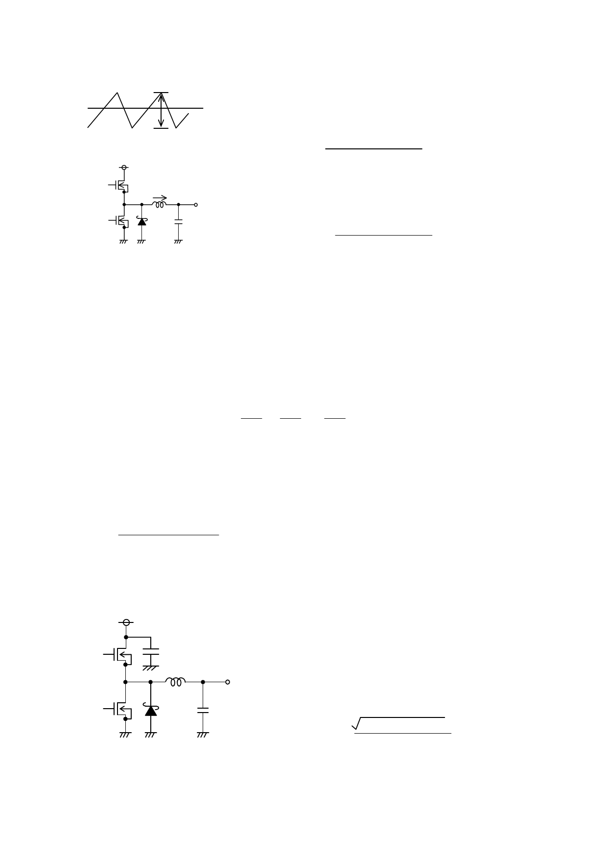
●Application component selection
(1) Setting the output L value
ΔIL
Fig-17
VCC
IL
L
VOUT
Co
Fig-18
Output ripple current
The coil value significantly influences the output ripple current.
Thus, as seen in equation (5), the larger the coil, and the higher
the switching frequency, the lower the drop in ripple current.
ΔIL = (VCC-VOUT)×VOUT [A]・・・(5)
L×VCC×f
The optimal output ripple current setting is 30% of maximum current.
ΔIL = 0.3×IOUTmax.[A]・・・(6)
L = (VCC-VOUT)×VOUT [H]・・・(7)
ΔIL×VCC×f
(ΔIL:output ripple current f:switching frequency)
※Outputting a current in excess of the coil current rating will cause magnetic saturation of the coil and decrease
efficiency.
Please establish sufficient margin to ensure that peak current does not exceed the coil current rating.
※Use low resistance (DCR, ACR) coils to minimize coil loss and increase efficiency.
(2) Setting the output capacitor Co value
Select the output capacitor with the highest value for ripple voltage (VPP) tolerance and maximum drop voltage
(at rapid load change). The following equation is used to determine the output ripple voltage.
ΔIL
Vo
1
Step down ΔVPP = ΔIL × RESR +
×
×
[V]
Co
Vcc
f
Note: f:switching frequency
Be sure to keep the output Co setting within the allowable ripple voltage range.
※Please allow sufficient output voltage margin in establishing the capacitor rating. Note that low-ESR capacitors enable
lower output ripple voltage.
Also, to meet the requirement for setting the output startup time parameter within the soft start time range, please factor
in the conditions described in the capacitance equation (9) for output capacitors, below.
TSS × (Limit – IOUT)
Co ≦
VOUT
・・・ (9)
Tss: soft start time
ILimit:over current detection value(2/16)reference
Note: less than optimal capacitance values may cause problems at startup.
(3) Input capacitor selection
VIN
Cin
L
VOUT
Co
Fig-19
Input capacitor
The input capacitor serves to lower the output impedance of the power
source connected to the input pin (VCC). Increased power supply output
impedance can cause input voltage (VCC) instability, and may negatively
impact oscillation and ripple rejection characteristics. Therefore, be
certain to establish an input capacitor in close proximity to the VCC and
GND pins. Select a low-ESR capacitor with the required ripple current
capacity and the capability to withstand temperature changes without
wide tolerance fluctuations. The ripple current IRMSS is determined
using equation (10).
IRMS = IOUT × VOUT(VCC - VOUT) [A]・・・(10)
VCC
Also, be certain to ascertain the operating temperature, load range and
MOSFET conditions for the application in which the capacitor will be used,
since capacitor performance is heavily dependent on the application’s
input power characteristics, substrate wiring and MOSFET gate drain
capacity.
8/28
Share Link: