WME128K8-120DEQA 查看數據表(PDF) - White Electronic Designs Corporation
零件编号
产品描述 (功能)
生产厂家
WME128K8-120DEQA Datasheet PDF : 11 Pages
| |||
White Electronic Designs
WME128K8-XXX
ABSOLUTE MAXIMUM RATINGS
Parameter
Symbol
Unit
Operating Temperature
TA
-55 to +125
°C
Storage Temperature
TSTG
-65 to +150
°C
Signal Voltage Relative to GND VG
-0.6 to + 6.25
V
Voltage on OE# and A9
-0.6 to +13.5
V
NOTE:
Stresses above those listed under "Absolute Maximum Ratings" may cause permanent
damage to the device. This is a stress rating only and functional operation of the device
at these or any other conditions above those indicated in the operational sections of
this specification is not implied. Exposure to absolute maximum rating conditions for
extended periods may affect device reliability.
RECOMMENDED OPERATING CONDITIONS
Parameter
Supply Voltage
Input High Voltage
Input Low Voltage
Operating Temp. (Mil.)
Operating Temp. (Ind.)
Symbol
VCC
VIH
VIL
TA
TA
Min
Max Unit
4.5
5.5
V
2.0 VCC + 0.3 V
-0.5
+0.8
V
-55
+125 °C
-40
+85
°C
TRUTH TABLE
CS# OE# WE#
H
X
X
L
L
H
L
H
L
X
H
X
X
X
H
X
L
X
Mode
Standby
Read
Write
Out Disable
Write
Inhibit
Data I/O
High Z
Data Out
Data In
High Z/Data Out
CAPACITANCE
TA = +25°C
Parameter
Input Capacitance
Output Capacitance
Symbol
CIN
COUT
Conditions
VIN = 0 V, f = 1MHz
VI/O = 0 V, f = 1MHz
This parameter is guaranteed by design but not tested.
Max Unit
20 pF
20 pF
DC CHARACTERISTICS
VCC = 5.0V, VSS = 0V, -55°C ≤ TA ≤ +125°C
Parameter
Input Leakage Current
Output Leakage Current
Operating Supply Current
Standby Current
Output Low Voltage
Output High Voltage
Symbol Conditions
Min
Max
Unit
ILI
VCC = 5.5, VIN = GND to VCC
10
µA
ILO
CS# = VIH, OE# = VIH, VOUT = GND to VCC
10
µA
ICC
CS# = VIL, OE# = VIH, f = 5MHz, VCC = 5.5
80
mA
ISB
CS# = VIH, OE# = VIH, f = 5MHz, VCC = 5.5
0.625
mA
VOL
IOL = 2.1mA, VCC = 4.5V
0.45
V
VOH
IOH = -400µA, VCC = 4.5V
2.4
V
NOTE: DC test conditions: VIH = VCC -0.3V, VIL = 0.3V
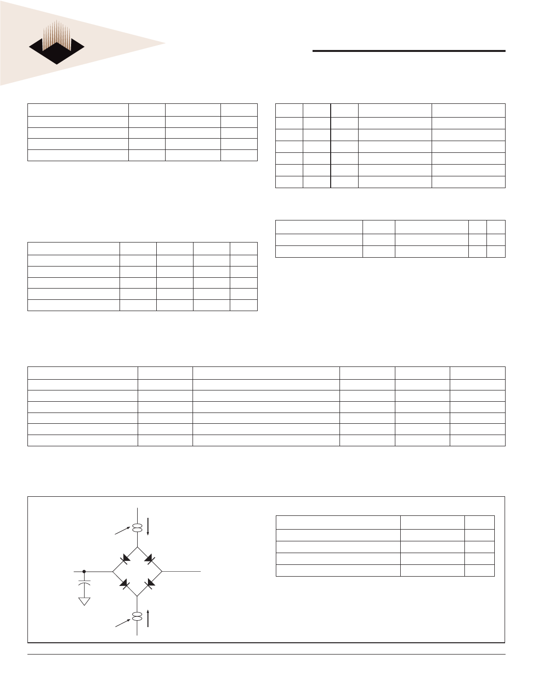
FIGURE 2 –
AC Test Circuit
IOL
Current Source
D.U.T
Ceff = 50 pf
IOH
Current Source
Vz ~~ 1.5V
Bipolar Supply
AC TEST CONDITIONS
Parameter
Input Pulse Levels
Input Rise and Fall
Input and Output Reference Level
Output Timing Reference Level
Typ
Unit
VIL = 0, VIH = 3.0
V
5
ns
1.5
V
1.5
V
Notes: VZ is programmable from -2V to +7V.
IOL & IOH programmable from 0 to 16mA.
Tester Impedance Z0 = 75Ω.
VZ is typically the midpoint of VOH and VOL.
IOL & IOH are adjusted to simulate a typical resistive load circuit.
ATE tester includes jig capacitance.
White Electronic Designs Corp. reserves the right to change products or specifications without notice.
January 2004
Rev. 5
2
White Electronic Designs Corporation • (602) 437-1520 • www.wedc.com
Share Link: 